

- RFQ
- BOM
-
Contact Us
Tel: +86-0755-83501315
Email: sales@sic-components.com


- Chinese
- English
- French
- German
- Portuguese
- Spanish
- Russian
- Japanese
- Korean
- Arabic
- Irish
- Greek
- Turkish
- Italian
- Danish
- Romanian
- Indonesian
- Czech
- Afrikaans
- Swedish
- Polish
- Basque
- Catalan
- Esperanto
- Hindi
- Lao
- Albanian
- Amharic
- Armenian
- Azerbaijani
- Belarusian
- Bengali
- Bosnian
- Bulgarian
- Cebuano
- Chichewa
- Corsican
- Croatian
- Dutch
- Estonian
- Filipino
- Finnish
- Frisian
- Galician
- Georgian
- Gujarati
- Haitian
- Hausa
- Hawaiian
- Hebrew
- Hmong
- Hungarian
- Icelandic
- Igbo
- Javanese
- Kannada
- Kazakh
- Khmer
- Kurdish
- Kyrgyz
- Latin
- Latvian
- Lithuanian
- Luxembou..
- Macedonian
- Malagasy
- Malay
- Malayalam
- Maltese
- Maori
- Marathi
- Mongolian
- Burmese
- Nepali
- Norwegian
- Pashto
- Persian
- Punjabi
- Serbian
- Sesotho
- Sinhala
- Slovak
- Slovenian
- Somali
- Samoan
- Scots Gaelic
- Shona
- Sindhi
- Sundanese
- Swahili
- Tajik
- Tamil
- Telugu
- Thai
- Ukrainian
- Urdu
- Uzbek
- Vietnamese
- Welsh
- Xhosa
- Yiddish
- Yoruba
- Zulu
- Kinyarwanda
- Tatar
- Oriya
- Turkmen
- Uyghur
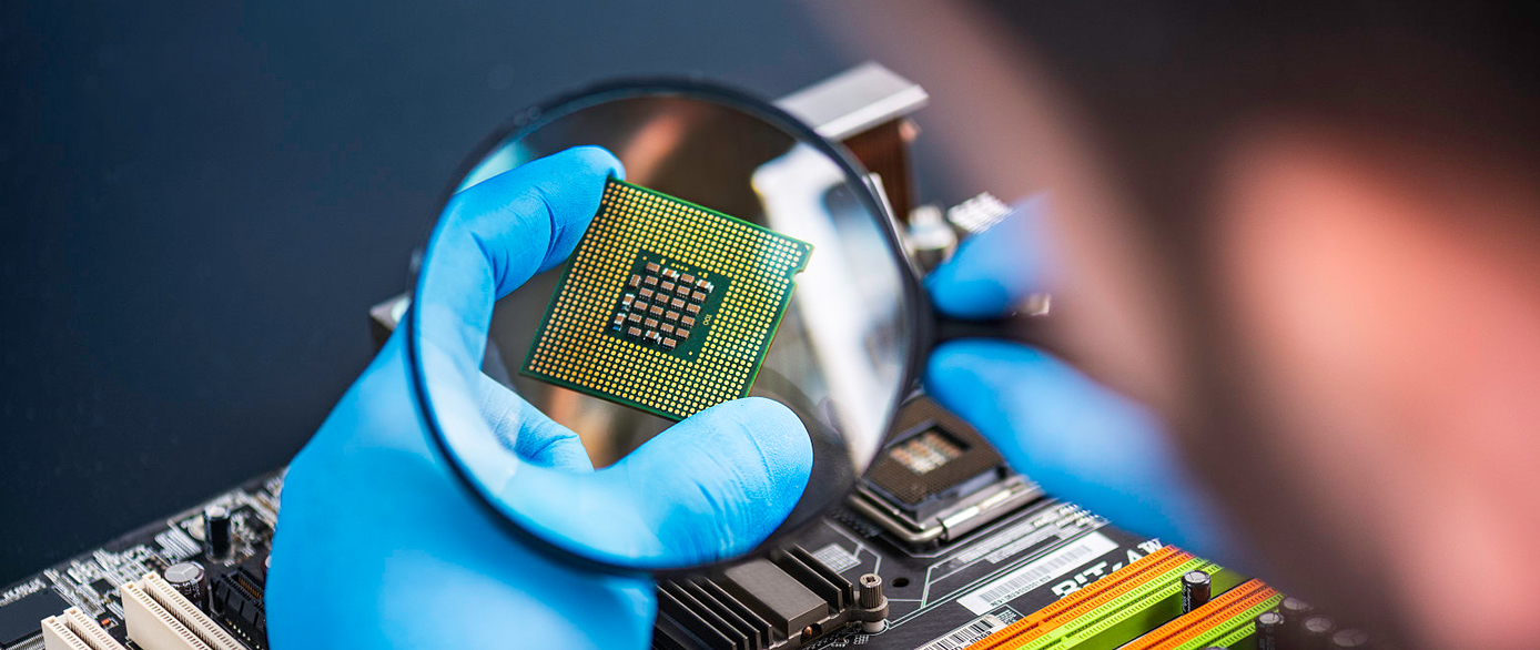
Clock Buffers
What Are Clock Buffers ICs?
Clock buffer ICs (https://www.sic-components.com/integrated-circuits-ics/clocktiming/clock-buffers-drivers) are integrated circuits that amplify, split, and distribute clock signals to multiple devices in a system. They isolate the clock signal source from the load, provide multiple controllable outputs, and can work as level shifters due to their separate power supplies for outputs or input/output.
How Do Clock Buffers ICs Work?
Clock buffer ICs (https://www.sic-components.com/integrated-circuits-ics/clocktiming/clock-buffers-drivers) create derivatives, variants, or copies of the reference clock, which is usually from a crystal oscillator or a clock generator. The goal is to scale the outputs and create a more distributive pathway for these outputs. They don't alter the frequency properties of the input signal, minimizing the additive noise during the buffering stage.
Types of Clock Buffers ICs
Single - ended output buffers: Usually LVCMOS (Low Voltage Complementary Metal - Oxide - Semiconductor), suitable for some applications that don't require high - speed or high - noise - immunity.
Differential output buffers: Such as LVPECL (Low Voltage Positive Emitter Coupled Logic), HSTL (High - Speed Transceiver Logic), or LVDS (Low Voltage Differential Signaling). They have better anti - interference ability and are suitable for high - speed and long - distance signal transmission.
Clock buffers also have various types in terms of maximum operating input frequency, maximum supply current, and number of pins. There are also ultra - low - jitter and low - skew clock buffers for applications requiring high - precision timing.
Functions of Clock Buffers ICs
Signal amplification and splitting: Amplify the input clock signal and split it into multiple copies for distribution to multiple devices in the system.
Isolation of source and load: Prevent the load from affecting the clock signal source, ensuring the stability of the source.
Improve signal integrity: Reduce jitter, skew, and noise of the clock signal, improving the accuracy and reliability of data transfer and device operation.
Level shifting: Adjust the voltage level of the clock signal to meet the requirements of different devices.
Advantages and disadvantages of Clock Buffers ICs
Advantages:
Reduced jitter: Can reduce the jitter of clock signals to acceptable levels, ensuring reliable and accurate timing.
Increased fan - out: Increase the number of devices that can be driven by a single clock signal without degrading system performance.
Improved signal integrity: By reducing noise and skew, the signal quality is improved, ensuring reliable and accurate data transfer.
High configurability: Allow users to adjust output frequency, duty cycle, and amplitude to meet specific application requirements.
Disadvantages:
Limited by power supply and frequency range: Some clock buffers have specific requirements for power supply voltage and current, and there may be limitations in the operating frequency range, which need to be carefully selected according to the application requirements.
Cost and complexity: High - performance clock buffer ICs may be relatively expensive, and the integration of multiple clock buffers in the circuit may increase the complexity of the circuit design and debugging.
Applications of Clock Buffers ICs
High - speed instrumentation and line receivers: Ensure accurate clock signals in high - speed data acquisition and transmission to improve measurement accuracy and signal reception quality.
Converter clocking: Provide stable clock signals for analog - to - digital converters and digital - to - analog converters to ensure accurate conversion of signals.
Automated test equipment (ATE): Ensure the synchronization and accuracy of various test signals in ATE to improve the reliability and accuracy of testing.
Wireless and wired communications: In communication systems such as base stations and routers, they ensure the accurate transmission and reception of data by providing stable clock signals.
Medical and industrial imaging: Such as in medical imaging equipment like CT scanners and industrial non - destructive testing equipment, they ensure the synchronization of image data acquisition and processing to improve image quality.
How to Choose Clock Buffers ICs ?
Frequency requirements: Select a clock buffer that can provide the required frequency range and accuracy according to the specific clock frequency requirements of the application.
Jitter and skew requirements: For applications with high - speed and high - precision requirements, choose clock buffers with low jitter and low skew to ensure the stability and accuracy of the clock signal.
Output type and number: Select the appropriate output type (single - ended or differential) and the number of outputs according to the needs of the connected devices.
Power consumption: For battery - powered or power - sensitive applications, choose clock buffers with low power consumption to extend battery life or meet power - saving requirements.
Package type: Consider the package type of the clock buffer and its compatibility with the circuit board design to ensure easy integration into the system.
Overview of SIC's Clock Buffers ICs (https://www.sic-components.com/integrated-circuits-ics/clocktiming/clock-buffers-drivers)
SIC offers a variety of clock buffer ICs to meet different application needs. Their products have the characteristics of high performance, reliability, and flexibility. For example, some clock buffers can generate high - frequency signals with low jitter and low skew, which are suitable for applications requiring precise timing. In addition, SIC's clock buffers also focus on low - power design, which is suitable for battery - powered devices, and have the advantages of compact packaging and easy integration with other components.
https://www.sic-components.com/integrated-circuits-ics/clocktiming/clock-buffers-drivers
Hot Products
View More-
NB3M8T3910GMNTWG onsemi
-
CY7B991V-2JCT Cypress Semiconductor Corp
-
PI6C5946002ZHIEX Diodes Incorporated
-
CY7B9973V-AC Cypress Semiconductor Corp
-

CG7873AAT Infineon Technologies
-
8S89202BKILF Renesas Electronics America Inc
-
8T30006PGGI Renesas Electronics America Inc
-
CG8607AA Infineon Technologies
-
PL130-07AQC Microchip Technology
-
MAX9312ETJ+TGH7 Analog Devices Inc./Maxim Integrated
-
100EL11M Fairchild Semiconductor
-
CY7B992-2JC Infineon Technologies
Related Blogs
-
2025 / 07 / 09
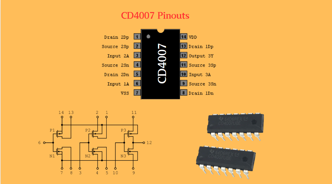
CD4007: A Comprehensive Analysis of a Multifunctional CMOS Integrated Circuit
In the field of modern electronic technology, CMOS (Complementary Metal-Oxide-Semiconductor) integrated circuits have become core components in digital and analog circuit design due to their low power consumption, high integration, and excellent compatibility. As a classic CMOS device, the CD4007 oc...
-
2025 / 07 / 07
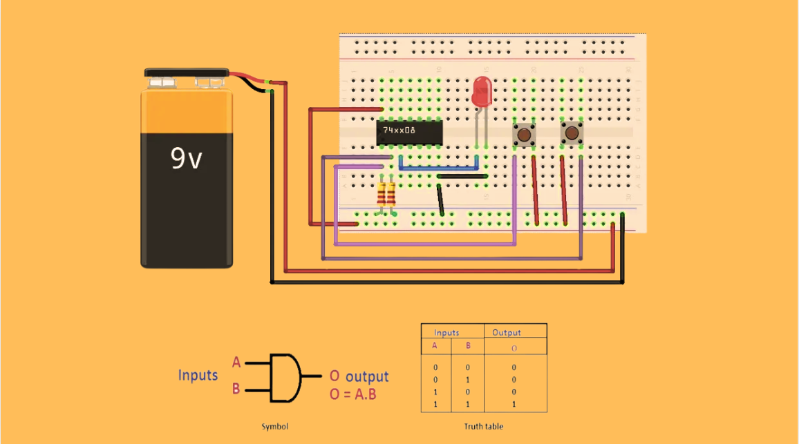
Understanding IC 7408: A Fundamental Component in Digital Logic Design
In the vast and intricate realm of digital electronics, integrated circuits (ICs) serve as the building blocks that enable the creation of complex and powerful systems. Among these, the IC 7408 holds a special place as a fundamental component in digital logic design. This article aims to provide a c...
-
2025 / 07 / 04
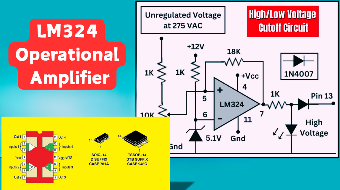
LM324 Operational Amplifier Comprehensive Guide: Pins, Applications, Packaging, and Datasheet
The LM324 is a low-cost integrated circuit featuring four independent operational amplifiers (op-amps), renowned for its wide voltage adaptability, low power consumption, and high reliability in industrial and consumer electronics. With a single-supply voltage range of 3V to 32V (or dual-supply rang...
-
2025 / 07 / 02
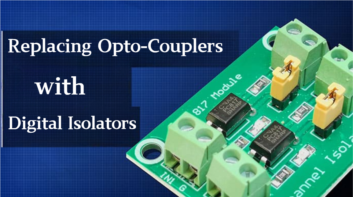
A Comprehensive Guide to Replacing Opto-Couplers with Digital Isolators: From Principles to Practice
In the ever-evolving landscape of electronic design, the transition from opto-couplers to digital isolators marks a pivotal shift in isolation technology. For decades, opto-couplers have been the cornerstone of electrical isolation in industrial control, medical devices, and power systems, relying o...
-
2025 / 06 / 30
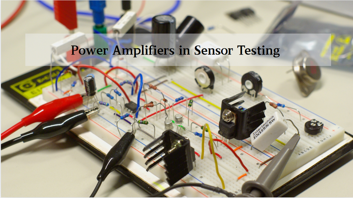
Multivariate Application Analysis of Power Amplifiers in Sensor Testing
In the field of modern sensor testing, power amplifiers (PAs) serve as core components and play an indispensable role. From amplifying weak signals to simulating complex physical environments, power amplifiers provide solid guarantees for the precise testing of sensor performance through their uniqu...
-
2025 / 06 / 28
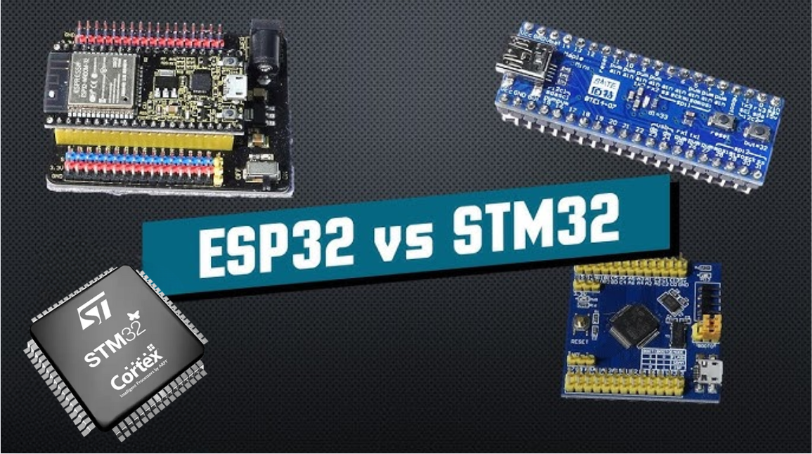
ESP32 vs STM32: Which Microcontroller Suits You Better?
In the field of embedded development, both ESP32 and STM32 are highly favored microcontrollers, each with unique features and advantages. When facing project development, how do you choose between them? This requires comprehensive consideration of multiple factors. The following detailed comparison ...
-
2025 / 06 / 26
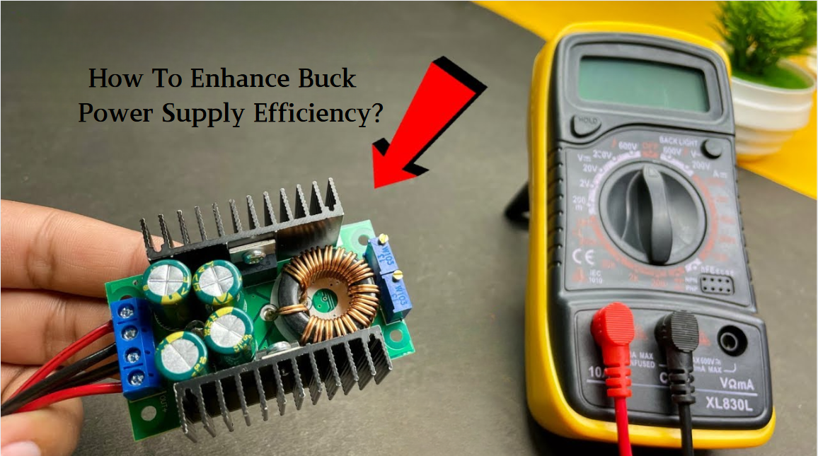
Key Strategies to Enhance Buck Power Supply Efficiency
Improving the efficiency of Buck (step-down) switching power supplies requires a multi-dimensional approach targeting energy loss sources, including component selection, topology optimization, control strategies, and thermal management. Below are core strategies and engineering practices:...
-
2025 / 06 / 26
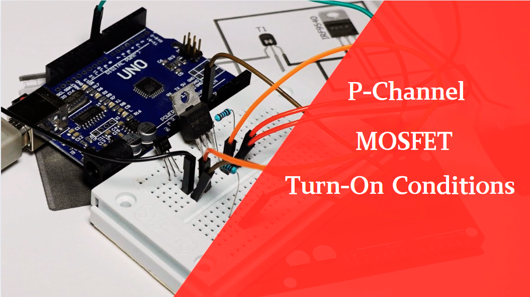
P-Channel MOSFET Turn-On Conditions
The turn-on conditions for a P-channel MOSFET (PMOS) are inverse to those of an N-channel MOSFET (NMOS), primarily governed by the relationship between the gate-source voltage (VGS) and the threshold voltage (Vth), along with voltage polarity. Here are the key points:A PMOS turns on when its gate vo...
-
2025 / 06 / 24
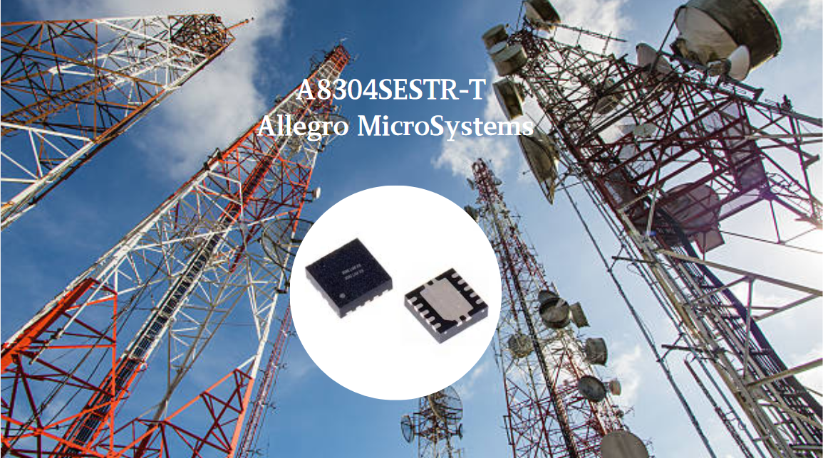
A8304SESTR-T Allegro MicroSystems-Single LNB Supply and Control Voltage Regulator
The Allegro MicroSystems A8304SESTR-T is a single-channel Low Noise Block Regulator (LNBR). It integrates a monolithic boost converter with MOSFET, current sensing, and compensation. Featuring a 704 kHz switching frequency, it uses few external components. With an I²C-compatible interface, it offers...
-
2025 / 06 / 20
EG25GGC-128-SGNS by Quectel Wireless Solutions Co., Ltd: Features,Symbol,Footprint and Datasheet
The Quectel EG25GGC - 128 - SGNS is an LTE Cat 4 module optimized for M2M and IoT. Supporting 3GPP Rel. 11, it offers up to 150Mbps downlink and 50Mbps uplink. With global LTE/UMTS/GSM coverage, it's backward - compatible with EDGE/GPRS. Featuring multi - constellation GNSS (GPS, GLONASS, BeiDou, et...


2000+
Daily average RFQ Volume

30,000,000
Standard Product Unit

2800+
Worldwide Manufacturers

15,000 m2
In-stock Warehouse
 Wishlist (0 Items)