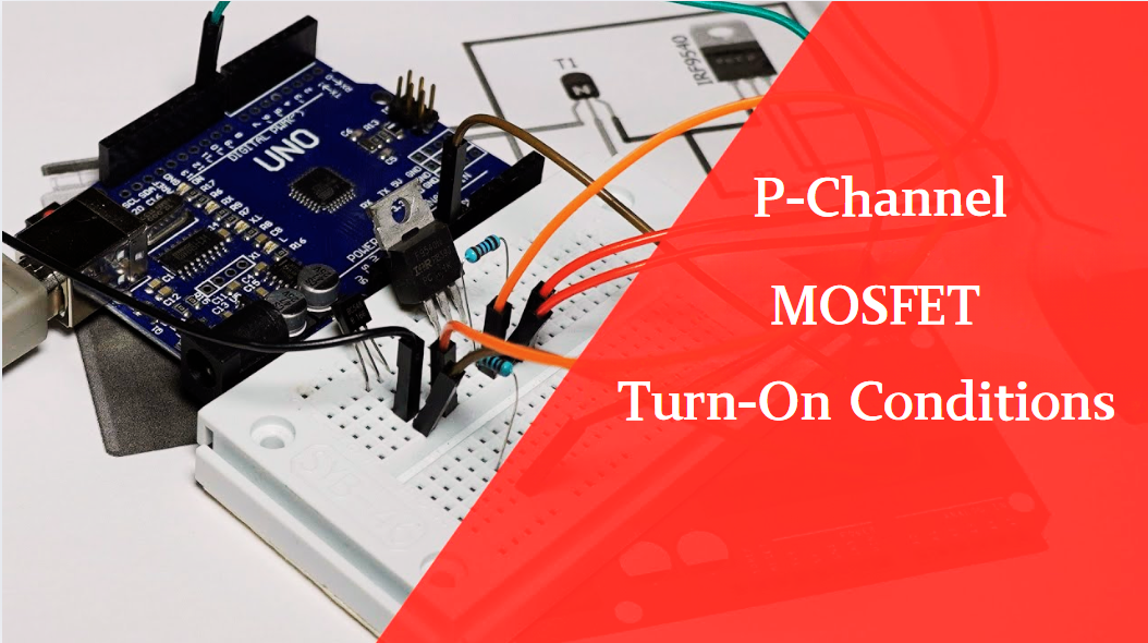
The turn-on conditions for a P-channel MOSFET (PMOS) are inverse to those of an N-channel MOSFET (NMOS), primarily governed by the relationship between the gate-source voltage (VGS) and the threshold voltage (Vth), along with voltage polarity. Here are the key points:

1. Core Turn-On Conditions
The necessary condition for a PMOS to conduct is:VGS≤Vth(where Vth is negative)
VGS=VG−VS (VG = gate voltage, VS = source voltage).
Since Vth for PMOS is typically negative (e.g., -1V, -2V), the gate voltage must be significantly lower than the source voltage to satisfy VGS≤Vth.
Example:
If Vth=−2V and VS=+5V, then:VG−5V≤−2V⟹VG≤+3V
The PMOS turns on when VG drops below 3V.
2. Comparison with N-Channel MOSFET (NMOS)
| Characteristic | P-Channel MOSFET (PMOS) | N-Channel MOSFET (NMOS) |
|---|---|---|
| Turn-On Condition | VGS≤Vth (Vth negative) | VGS≥Vth (Vth positive) |
| Voltage Polarity | Gate voltage must be lower than source | Gate voltage must be higher than source |
| Typical Application | High-side switches (source connects to V+) | Low-side switches (source connects to GND) |
| Body Diode Direction | Source (S) → Drain (D) | Drain (D) → Source (S) |
3. Key Practical Considerations
High-Side Switching:
PMOS is commonly used in high-side switch circuits (source connected to the power supply, drain to the load). A low gate voltage turns it on, grounding the load. Example: In battery-powered circuits, PMOS controls power to the load, simplifying logic-level control.
Voltage Polarity & Drive Circuit:
PMOS requires a pull-down driver (e.g., an NPN transistor or NMOS) to lower the gate voltage below the source.
In CMOS logic (e.g., inverters), PMOS pulls the output high, complementing NMOS which pulls low.
Body Diode Effects:
PMOS has an internal body diode from source to drain. If the drain voltage exceeds the source voltage, the diode conducts, potentially causing unintended current flow. Designers must avoid reverse voltages or add protective measures.
4. Summary
PMOS Conducts⟺VG<VS+∣Vth∣(where Vth is negative)
Hot-selling products of SIC
71421LA55J8 UPD44165184BF5-E40-EQ3-A SST39VF800A-70-4C-B3KE IS66WV1M16DBLL-55BLI-TR AS4C32M16SB-7BIN W25Q16FWSNIG
AS7C34098A-20JIN 752369-581-C W957D6HBCX7I TR IS61LPS12836EC-200B3LI MX25L12875FMI-10G QG82915PL
Product information is from SIC Electronics Limited. If you are interested in the product or need product parameters, you can contact us online at any time or send us an email: sales@sic-chip.com.


 Wishlist (0 Items)