

- RFQ
- BOM
-
Contact Us
Tel: +86-0755-83501315
Email: sales@sic-components.com


- Chinese
- English
- French
- German
- Portuguese
- Spanish
- Russian
- Japanese
- Korean
- Arabic
- Irish
- Greek
- Turkish
- Italian
- Danish
- Romanian
- Indonesian
- Czech
- Afrikaans
- Swedish
- Polish
- Basque
- Catalan
- Esperanto
- Hindi
- Lao
- Albanian
- Amharic
- Armenian
- Azerbaijani
- Belarusian
- Bengali
- Bosnian
- Bulgarian
- Cebuano
- Chichewa
- Corsican
- Croatian
- Dutch
- Estonian
- Filipino
- Finnish
- Frisian
- Galician
- Georgian
- Gujarati
- Haitian
- Hausa
- Hawaiian
- Hebrew
- Hmong
- Hungarian
- Icelandic
- Igbo
- Javanese
- Kannada
- Kazakh
- Khmer
- Kurdish
- Kyrgyz
- Latin
- Latvian
- Lithuanian
- Luxembou..
- Macedonian
- Malagasy
- Malay
- Malayalam
- Maltese
- Maori
- Marathi
- Mongolian
- Burmese
- Nepali
- Norwegian
- Pashto
- Persian
- Punjabi
- Serbian
- Sesotho
- Sinhala
- Slovak
- Slovenian
- Somali
- Samoan
- Scots Gaelic
- Shona
- Sindhi
- Sundanese
- Swahili
- Tajik
- Tamil
- Telugu
- Thai
- Ukrainian
- Urdu
- Uzbek
- Vietnamese
- Welsh
- Xhosa
- Yiddish
- Yoruba
- Zulu
- Kinyarwanda
- Tatar
- Oriya
- Turkmen
- Uyghur
Which capacitor is preferred for high frequency circuits?
In high-frequency circuits, the selection of capacitors is critical to ensure minimal signal loss, stable performance, and reduced interference. Not all capacitors are suitable for high-frequency applications due to their inherent physical properties, such as equivalent series resistance (ESR), equivalent series inductance (ESL), and dielectric losses. This article explores the key factors influencing capacitor performance at high frequencies and highlights the most preferred types for such circuits. https://www.sic-components.com/capacitors
1. Key Factors Affecting Capacitor Performance in High-Frequency Circuits
1.1 Equivalent Series Inductance (ESL)
ESL is the parasitic inductance caused by the capacitor’s lead wires, terminals, and internal structure. At high frequencies, even small inductance can introduce significant impedance, leading to resonance and signal distortion. Capacitors with lower ESL are essential to maintain low impedance.
1.2 Equivalent Series Resistance (ESR)
ESR represents the resistive losses in a capacitor, including those from the dielectric, electrodes, and terminals. High ESR at high frequencies can cause power dissipation and voltage ripple, reducing circuit efficiency.
1.3 Dielectric Material and Loss Tangent (tanδ)
The dielectric material determines the capacitor’s frequency response. A low loss tangent (tanδ, the ratio of energy loss to stored energy) is critical to minimize dielectric heating and signal attenuation at high frequencies.
1.4 Self-Resonant Frequency (SRF)
Each capacitor has a self-resonant frequency where its capacitive reactance equals its ESL, resulting in maximum impedance. Beyond SRF, the capacitor behaves inductively, making it unsuitable for filtering or decoupling. High-frequency applications require capacitors with SRF well above the operating frequency.
2. Preferred Capacitor Types for High-Frequency Circuits
2.1 Ceramic Capacitors (MLCC - Multilayer Ceramic Chip Capacitors)
Structure and Material:
MLCCs consist of alternating ceramic dielectric layers and metal electrodes, offering low ESL due to their chip design (leadless or surface-mount). The most common high-frequency ceramic dielectrics include:
Class 1 (C0G/NP0): Made from temperature-stable materials (e.g., barium titanate), with extremely low tanδ (<0.001) and high SRF (up to GHz ranges), suitable for precision timing and resonant circuits.
Class 2 (X7R, X5R): Higher capacitance values but slightly higher tanδ and temperature sensitivity, used for general high-frequency decoupling.
Advantages:
Extremely low ESL and ESR, ideal for high-frequency filtering and bypassing.
Compact size and high reliability.
Wide availability in surface-mount packages (0201, 0402) for space-constrained designs.
Limitations:
Susceptible to voltage and temperature drift (Class 2 types).
Limited capacitance range (typically up to several μF).
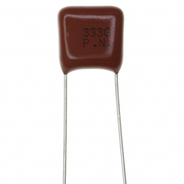
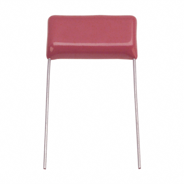
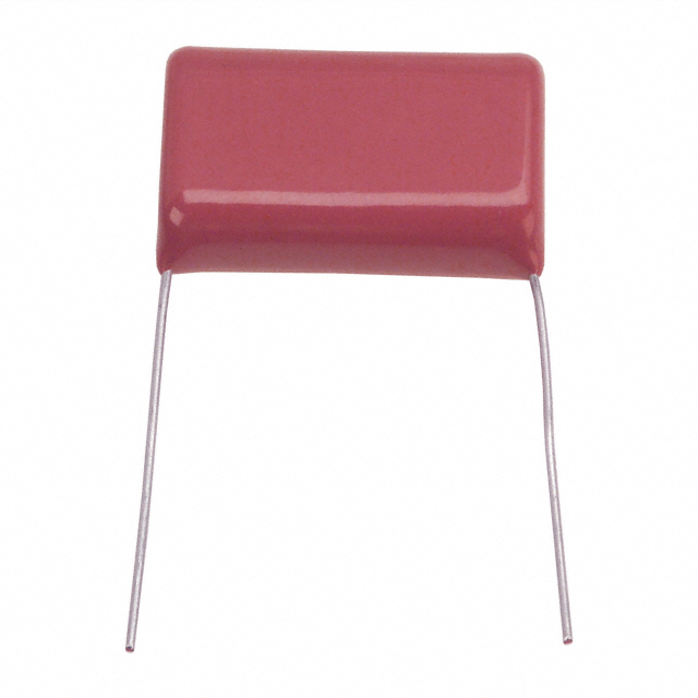
2.2 Film Capacitors (Polyester, Polypropylene, Polytetrafluoroethylene - PTFE)
Structure and Material:
Film capacitors use thin polymer films (e.g., polypropylene, PTFE) as dielectrics, wrapped or stacked with metal electrodes. Polypropylene (PP) film is particularly popular for high frequencies due to its:
Low tanδ (0.0005–0.002) and stable performance up to MHz ranges.
High breakdown voltage and self-healing properties (for metalized films).
Advantages:
Low ESL (especially in stacked or metalized designs) and minimal dielectric losses.
Good temperature stability and high current-carrying capacity.
Suitable for high-frequency power electronics, RF coupling, and audio applications.
Limitations:
Larger size compared to MLCCs for the same capacitance.
Higher cost for premium materials like PTFE.
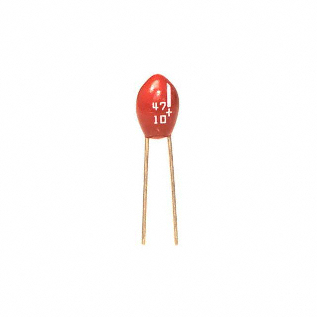
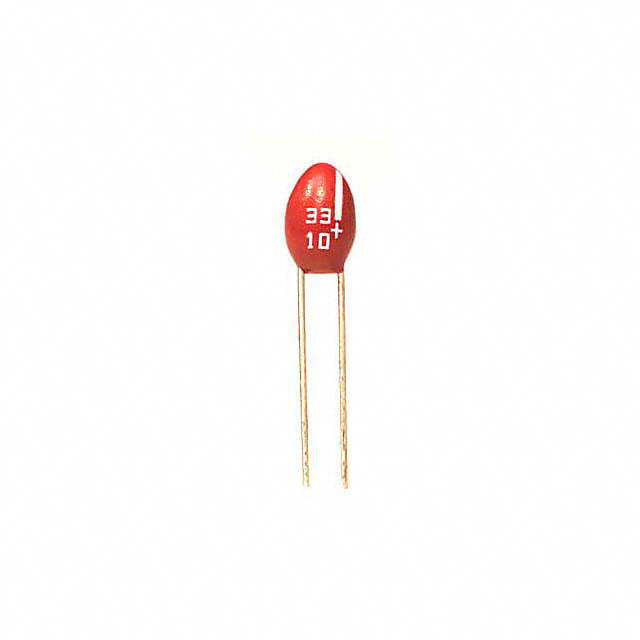
2.3 Silver Mica Capacitors
Structure and Material:
Mica capacitors use mica sheets as dielectrics with silver electrodes, often in a radial lead or chip format. Mica has exceptional electrical properties:
Extremely low tanδ (<0.0001) and high SRF (up to hundreds of MHz).
Excellent temperature and voltage stability.
Advantages:
Ultra-low losses and high precision, ideal for RF tuning, oscillators, and high-frequency filters.
Long-term stability and reliability.
Limitations:
Limited capacitance (typically up to 0.1 μF) and higher cost.
Larger size than MLCCs, making them less suitable for dense PCB designs.
2.4 Aluminum and Tantalum Electrolytic Capacitors (Limited Use Cases)
Considerations:
Traditional electrolytic capacitors (aluminum or tantalum) have high ESL and ESR, making them unsuitable for high-frequency applications. However, low-ESR variants (e.g., low-profile aluminum electrolytics or surface-mount tantalum) may be used in specific scenarios:
Low-ESR Aluminum Electrolytics: Used in power supplies for high-frequency ripple filtering (up to ~100 kHz), but not for RF or microwave circuits.
Tantalum Capacitors: Slightly lower ESR than aluminum, but still limited to lower frequencies (up to ~1 MHz) for decoupling in mixed-signal circuits.
Limitations:
High ESL and ESR cause significant losses at MHz frequencies.
Polarized design restricts usage in AC-coupled circuits.
3. High-Frequency Capacitor Applications
3.1 RF and Microwave Circuits
Use Cases: Antenna matching networks, RF filters, oscillators, and mixers.
Preferred Types:
MLCC (C0G/NP0) for low-loss tuning and coupling.
Silver mica capacitors for precise resonant circuits.
PTFE film capacitors for high-reliability RF components.
3.2 High-Speed Digital Electronics
Use Cases: Decoupling in microprocessors, high-speed data buses, and clock circuits.
Preferred Types:
MLCC (X7R/X5R) for bulk decoupling, paired with C0G/NP0 for high-frequency bypassing.
Low-ESR film capacitors for reducing voltage transients in power rails.
3.3 Power Electronics (Switching Converters)
Use Cases: Output filtering in DC-DC converters operating at 100 kHz to 1 MHz.
Preferred Types:
Low-ESR MLCCs for high-frequency ripple suppression.
Metalized polypropylene film capacitors for snubber circuits and EMI filtering.
4. Design Tips for High-Frequency Capacitor Implementation
Minimize Lead Length and Parasitic Inductance:
Use surface-mount capacitors (e.g., 0402, 0201) to reduce ESL.
Route traces to the capacitor terminals as short and wide as possible.
Parallel Capacitor Networks:
Combine low-capacitance, high-SRF MLCCs (e.g., 0.1 μF) with higher-capacitance film capacitors for broad-bandwidth decoupling.
This approach extends the effective frequency range by leveraging each capacitor’s optimal SRF.
Thermal and Environmental Considerations:
Avoid dielectrics with high temperature coefficients (e.g., X7R has better stability than Y5V).
Ensure proper airflow or thermal management for capacitors in high-power applications to prevent dielectric degradation.
Impedance Matching:
Calculate the capacitor’s reactance (Xc = 1/(2πfC)) to ensure it provides low impedance at the target frequency.
Use simulation tools (e.g., SPICE) to model capacitor behavior in the circuit.
5. Emerging Trends in High-Frequency Capacitor Technology
3D Packaging and Integrated Capacitors:
Embedded capacitors in PCBs or semiconductor packages reduce ESL by minimizing lead lengths, suitable for mmWave and high-density designs.
New Dielectric Materials:
Research into ceramics (e.g., barium strontium titanate) and nanocomposites aims to balance high capacitance with low losses at GHz frequencies.
Advanced Manufacturing Techniques:
Thin-film deposition and atomic layer deposition (ALD) enable smaller, more precise MLCCs with improved high-frequency performance.
Conclusion
For high-frequency circuits, the ideal capacitor balances low ESL, low ESR, minimal dielectric losses, and a high self-resonant frequency. Ceramic capacitors (especially MLCCs with C0G/NP0 dielectrics) are the go-to choice for most high-frequency applications due to their compact size and excellent high-frequency characteristics. Film capacitors (polypropylene, PTFE) and silver mica capacitors complement them in scenarios requiring higher stability or larger capacitance. By prioritizing dielectric material, package design, and parasitic effects, engineers can ensure optimal performance in RF, microwave, and high-speed digital systems. As technology advances, integrated and novel material solutions will further push the boundaries of capacitor performance in high-frequency environments.
https://www.sic-components.com/capacitors
Hot Products
View More-

ECQ-E1825KZ Panasonic Electronic Components
-
ECS-F1AE476K Panasonic Electronic Components
-
ECQ-P1H333GZ Panasonic Electronic Components
-
ECQ-E1335KZ Panasonic Electronic Components
-
ECS-F1AE107 Panasonic Electronic Components
-
ECS-F1VE155K Panasonic Electronic Components
-
ECQ-E1274KZ Panasonic Electronic Components
-
ECQ-E1155KZ Panasonic Electronic Components
-
ECS-F1AE226K Panasonic Electronic Components
-
ECQ-E1475KZ Panasonic Electronic Components
-
ECQ-E1125KZ Panasonic Electronic Components
-
ECS-F1AE336K Panasonic Electronic Components
Related Blogs
-
2025 / 06 / 30
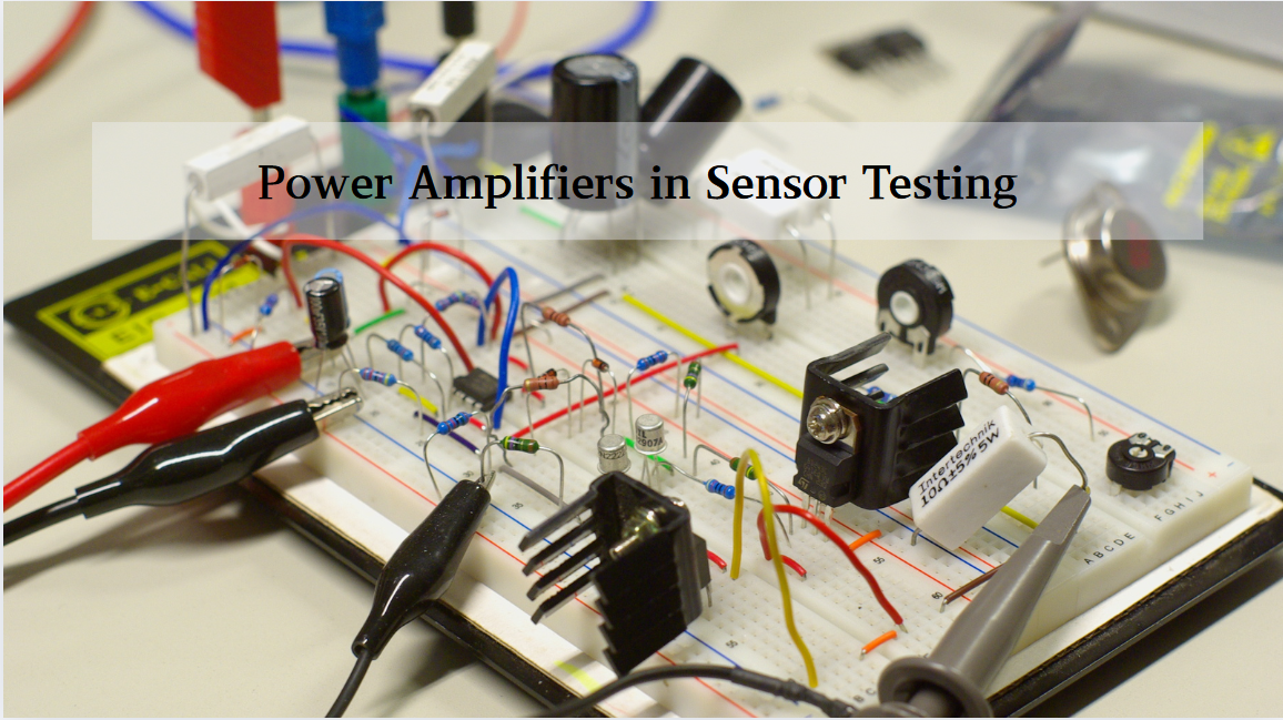
Multivariate Application Analysis of Power Amplifiers in Sensor Testing
In the field of modern sensor testing, power amplifiers (PAs) serve as core components and play an indispensable role. From amplifying weak signals to simulating complex physical environments, power amplifiers provide solid guarantees for the precise testing of sensor performance through their uniqu...
-
2025 / 06 / 28
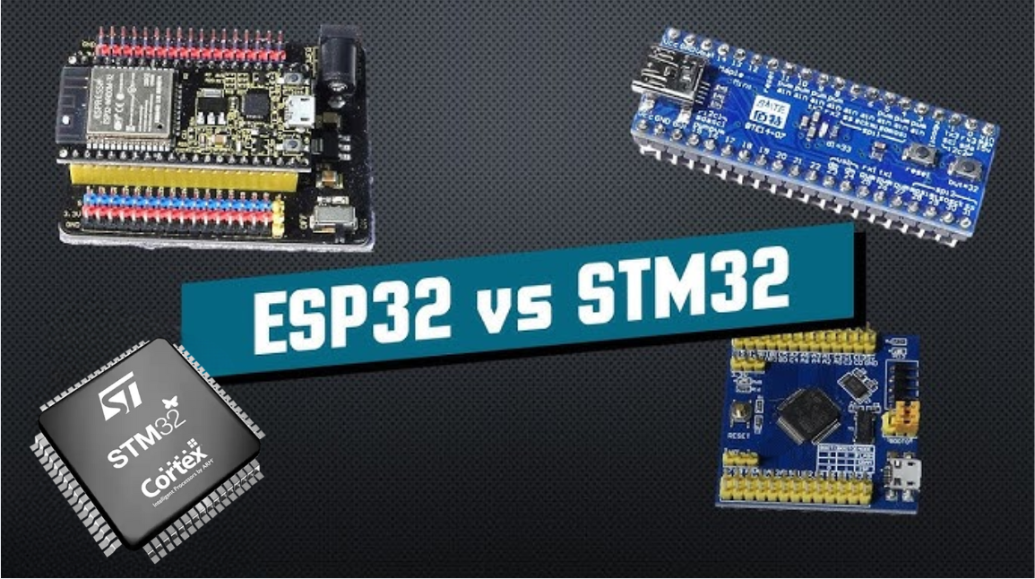
ESP32 vs STM32: Which Microcontroller Suits You Better?
In the field of embedded development, both ESP32 and STM32 are highly favored microcontrollers, each with unique features and advantages. When facing project development, how do you choose between them? This requires comprehensive consideration of multiple factors. The following detailed comparison ...
-
2025 / 06 / 26
Key Strategies to Enhance Buck Power Supply Efficiency
Improving the efficiency of Buck (step-down) switching power supplies requires a multi-dimensional approach targeting energy loss sources, including component selection, topology optimization, control strategies, and thermal management. Below are core strategies and engineering practices:...
-
2025 / 06 / 26
P-Channel MOSFET Turn-On Conditions
The turn-on conditions for a P-channel MOSFET (PMOS) are inverse to those of an N-channel MOSFET (NMOS), primarily governed by the relationship between the gate-source voltage (VGS) and the threshold voltage (Vth), along with voltage polarity. Here are the key points:A PMOS turns on when its gate vo...
-
2025 / 06 / 24
A8304SESTR-T Allegro MicroSystems-Single LNB Supply and Control Voltage Regulator
The Allegro MicroSystems A8304SESTR-T is a single-channel Low Noise Block Regulator (LNBR). It integrates a monolithic boost converter with MOSFET, current sensing, and compensation. Featuring a 704 kHz switching frequency, it uses few external components. With an I²C-compatible interface, it offers...
-
2025 / 06 / 20
EG25GGC-128-SGNS by Quectel Wireless Solutions Co., Ltd: Features,Symbol,Footprint and Datasheet
The Quectel EG25GGC - 128 - SGNS is an LTE Cat 4 module optimized for M2M and IoT. Supporting 3GPP Rel. 11, it offers up to 150Mbps downlink and 50Mbps uplink. With global LTE/UMTS/GSM coverage, it's backward - compatible with EDGE/GPRS. Featuring multi - constellation GNSS (GPS, GLONASS, BeiDou, et...

-
2025 / 06 / 17
STMicroelectronics STM32F413CGU6 Microcontroller: Datasheet, Performance, Features
The STMicroelectronics STM32F413CGU6 is an Arm® Cortex®-M4 based MCU with FPU, operating at up to 100 MHz for 125 DMIPS performance. It features 1MB Flash, 320KB SRAM, and interfaces like USB OTG FS, 3 CAN, ADC, 2 DAC, and multiple serial ports. With low-power modes (Sleep, Stop, Standby), it suits ...
-
2025 / 06 / 13
STMicroelectronics STM32F446ZCT6 -Microcontrollers: A Comprehensive Guide
The STMicroelectronics STM32F446ZCT6 is an ARM Cortex-M4-based MCU with FPU, running at up to 180 MHz. It features 256 KB Flash, 128 KB SRAM + 4 KB backup SRAM, and offers rich peripherals: USB OTG HS/FS, 2 CAN, 3 ADCs, 17 timers, and 20 communication interfaces. In LQFP144 package, industrial temp ...
-
2025 / 06 / 09
MC33887PNB NXP Semiconductors-Motor Drivers:A Comprehensive Guide
The NXP Semiconductors MC33887PNB is a 5.0 A H - bridge power IC with integrated load current feedback. It operates across a 5.0 V - 28 V voltage range, features low RDS(on) (120 mΩ typical), and supports up to 10 kHz PWM. With functions like active current limiting and fault reporting, it ensures r...
-
2025 / 06 / 07
A 16-bit Bus Transceiver: Why Choose the Texas Instruments SN74ACT16245QDLREP?
The Texas Instruments SN74ACT16245QDLREP is a high-performance 16-bit bus transceiver. Designed for harsh industrial and automotive environments, it operates reliably from -40°C to +125°C. With its dual 8-bit non-inverting 3-state architecture, it enables efficient bidirectional data transfer. It of...

2000+
Daily average RFQ Volume

30,000,000
Standard Product Unit

2800+
Worldwide Manufacturers

15,000 m2
In-stock Warehouse
 Wishlist (0 Items)