

- RFQ
- BOM
-
Contact Us
Tel: +86-0755-83501315
Email: sales@sic-components.com


- Chinese
- English
- French
- German
- Portuguese
- Spanish
- Russian
- Japanese
- Korean
- Arabic
- Irish
- Greek
- Turkish
- Italian
- Danish
- Romanian
- Indonesian
- Czech
- Afrikaans
- Swedish
- Polish
- Basque
- Catalan
- Esperanto
- Hindi
- Lao
- Albanian
- Amharic
- Armenian
- Azerbaijani
- Belarusian
- Bengali
- Bosnian
- Bulgarian
- Cebuano
- Chichewa
- Corsican
- Croatian
- Dutch
- Estonian
- Filipino
- Finnish
- Frisian
- Galician
- Georgian
- Gujarati
- Haitian
- Hausa
- Hawaiian
- Hebrew
- Hmong
- Hungarian
- Icelandic
- Igbo
- Javanese
- Kannada
- Kazakh
- Khmer
- Kurdish
- Kyrgyz
- Latin
- Latvian
- Lithuanian
- Luxembou..
- Macedonian
- Malagasy
- Malay
- Malayalam
- Maltese
- Maori
- Marathi
- Mongolian
- Burmese
- Nepali
- Norwegian
- Pashto
- Persian
- Punjabi
- Serbian
- Sesotho
- Sinhala
- Slovak
- Slovenian
- Somali
- Samoan
- Scots Gaelic
- Shona
- Sindhi
- Sundanese
- Swahili
- Tajik
- Tamil
- Telugu
- Thai
- Ukrainian
- Urdu
- Uzbek
- Vietnamese
- Welsh
- Xhosa
- Yiddish
- Yoruba
- Zulu
- Kinyarwanda
- Tatar
- Oriya
- Turkmen
- Uyghur
What is an inductor (coil)? Principle and Roles
In the field of electronic engineering, the inductor, as one of the three major passive components on a par with the resistor (R) and the capacitor (C), holds a pivotal position. It is usually denoted by the symbol "L", and its core function lies in maintaining a constant current state. The measure of the inductor's ability is the "inductance", with the unit being Henry (H).
I. Basic Structural Features
Winding Forms: Inductors have diverse winding forms. In most cases, they adopt the simple structure of a single-layer winding. However, there are also some inductors with multi-layer complex structures to meet different performance requirements.
Core Materials: In terms of core materials, there are inductors with a hollow structure. Besides, there are products with magnetic core structures such as ferrite and iron powder cores. Different core materials can significantly affect the performance of inductors.
Performance Relationship: The inductance is directly proportional to the square of the number of turns and the square of the radius of the inductor, and inversely proportional to the length of the coil. This characteristic determines that when designing and manufacturing inductors, the desired inductance can be achieved by adjusting these parameters.
II. In-depth Analysis of the Working Principle
Electromagnetic Induction Phenomenon: When current passes through a conductor, according to the right-hand screw rule, a magnetic field in the corresponding direction will be generated. For the coil winding of an inductor, the magnetic fields generated by each coil are superimposed on each other, forming a structure similar to an electromagnet (as shown in Figure 1). It is worth noting that this electromagnetic conversion is a reversible process, that is, a changing magnetic field can also induce current.
Analysis of Self-inductance Effect
Characteristics in DC Circuits (as shown in Figure 2): In a DC circuit, when the current suddenly changes, the inductor will generate an induced electromotive force to oppose the change in current. When the current stabilizes, the magnetic flux no longer changes, and at this time, the induced electromotive force disappears. Eventually, the inductor exhibits the characteristic of unobstructed DC in the DC circuit.
Characteristics in AC Circuits (as shown in Figure 3): In an AC circuit, the performance of the inductor is different. When the rate of change of the current reaches its maximum, the induced voltage also reaches its maximum value; while at the extreme points of the current, the voltage is zero. In addition, the voltage lags behind the current in phase by 1/4 of a cycle, following the formula V = L・ΔI/Δt.
Frequency Response Characteristics
Low-frequency Stage: In a low-frequency environment, the inductor exhibits obvious inductive reactance (XL = 2πfL), which enables it to effectively process and control low-frequency signals.
High-frequency Stage: As the frequency increases, the distributed capacitance effect of the inductor becomes significant. When the self-resonant frequency point is reached, the inductive reactance and the capacitive reactance cancel each other out; and in the ultra-high frequency stage, the capacitive characteristics of the inductor will dominate.
III. Main Application Areas
Applications in Power Circuits
Typical Functions: In power circuits, the inductor has the characteristics of allowing DC to pass through while blocking AC. At the same time, it can cooperate with a capacitor to achieve the function of smooth filtering and effectively suppress high-frequency noise.
Special Types: Among them, power inductors can handle large currents, and chokes are mainly used for ripple suppression to ensure the stability of the power output.
Applications in High-frequency Circuits
Special Requirements: In high-frequency circuits, there are high requirements for inductors, such as the need to have a high Q factor (quality factor), low parasitic capacitance, and a stable self-resonant frequency.
Typical Scenarios: Commonly found in the field of wireless communication (MHz - GHz frequency band), it is used for the selection of radio frequency signals and the construction of impedance matching networks to ensure the high-quality transmission of signals.
Applications in Power Transformers
Working Principle: Power transformers work based on the mutual inductance effect, and the turns ratio of the primary/secondary windings determines the voltage transformation ratio.
Derived Types: Including intermediate frequency transformers (IFTs), audio transformers, and power transmission transformers, etc., which are widely used in different power transmission and conversion scenarios.
IV. Detailed Explanation of Inductor Types
Wound Inductors
Structural Features: Wound inductors are formed by spirally winding wires, and different magnetic core materials can be selected according to needs.
Advantages: This structure endows wound inductors with the advantages of large current-carrying capacity and the ability to achieve high inductance values.
Typical Applications: Commonly used in power filtering and power conversion circuits to meet the higher requirements for current and inductance.
Multi-layer Chip Inductors
Manufacturing Process: Multi-layer chip inductors are manufactured by stacking ferrite/ceramic sheets and printing conductor patterns through screen printing.
Characteristics: This type of inductor integrates distributed capacitance and has the characteristics of a miniaturized design, making it suitable for the application requirements of surface-mounted circuits and high-frequency electronic devices.
V. Analysis of Professional Terms
Name Definition Features Typical Application Scenarios
Choke Power inductor with large inductance Power AC-DC conversion
Common-mode Filter Double-winding integrated structure Noise suppression for USB/HDMI interfaces
Toroidal Coil Closed magnetic circuit design, low magnetic leakage High-stability high-frequency circuits
Adjustable Inductor The position of the magnetic core can be adjusted Tuning of radio frequency circuits
Color-code Inductor Parameters marked by color rings Traditional electronic devices
VI. Key Technical Parameters for Selection
Basic Parameters: Including inductance (μH - mH), rated current (DC/AC), and DC resistance (DCR), etc. These parameters are the basic basis for selecting inductors.
Frequency Characteristics: Frequency characteristic parameters such as the self-resonant frequency (SRF) and the Q factor (quality factor) play a crucial role in the performance of inductors in different frequency environments.
Reliability Indicators: Reliability indicators such as temperature rise characteristics, saturation current, and insulation withstand voltage ensure the stability and safety of inductors in practical applications.
Mechanical Parameters: Mechanical parameters such as package size, terminal type, and installation method affect the installation and use of inductors in circuits.
VII. Key Points of Application Design
Power Circuit Design
LC Filter Combination: When designing an LC filter combination, it is necessary to accurately calculate the cut-off frequency and fully consider the influence of the ripple current.
Layout Requirements: Reasonably arrange the inductor to avoid magnetic field interference, and optimize the large current path to improve the performance of the power circuit.
High-frequency Circuit Design
Parasitic Parameter Control: Effectively control the parasitic parameters of the inductor by measures such as reducing the distributed capacitance and optimizing the winding process.
Impedance Matching: Use the Smith chart for impedance matching and verify the rationality of the design through S-parameter simulation to ensure the signal transmission quality of the high-frequency circuit.
Thermal Management Strategy
Loss Calculation: Accurately calculate the copper loss and iron loss to evaluate the heating situation of the inductor during operation.
Heat Dissipation Design: Design a reasonable heat dissipation path and follow the temperature derating criteria to ensure that the inductor operates within an appropriate temperature range.
VIII. Future Development Trends
Material Innovation: The application of new materials such as nanocrystalline alloys and low-temperature co-fired ceramics (LTCC) will bring new breakthroughs in the performance improvement of inductors.
Integration Technology: The development of integration technologies such as embedded inductors and IPD passive integration enables inductors to better integrate with other electronic components, achieving the miniaturization and high-performance of circuits.
High-frequency Applications: With the continuous development of high-frequency application fields such as 5G millimeter-wave devices and automotive radar systems, higher requirements are put forward for the high-frequency performance of inductors, which also provides broad space for the innovation of inductor technology.
Intelligent Development: In the future, inductors are expected to realize intelligent functions such as parameter self-detection and programmable inductance, further enhancing their application value in electronic systems.
By comprehensively and deeply understanding the working principle of inductors and mastering various application techniques, engineers can fully leverage the performance advantages of inductors in circuit design. With the rapid development of wireless communication and power electronics technologies, inductor technology will continue to innovate, providing crucial support and guarantee for the development of modern electronic systems.
Introducing our line of Coil Inductors, designed to provide reliable and efficient performance in a wide range of applications. Our Coil Inductors are meticulously engineered to deliver superior inductance, resonance, and impedance characteristics, ensuring optimal performance in electronic circuits. Constructed with high-quality materials and precision manufacturing processes, our Coil Inductors are built to withstand rigorous use and deliver consistent results. Whether you need inductors for power supplies, telecommunications equipment, or electronic devices, our Coil Inductors are the perfect choice for demanding applications. We offer a variety of Coil Inductors with different inductance values, current ratings, and package sizes to meet the diverse needs of our customers. With our commitment to quality and performance, you can trust our Coil Inductors to provide reliable and efficient operation in your electronic systems. Choose our Coil Inductors for exceptional reliability and performance in your electronic applications.
https://www.sic-components.com/inductors-coils-chokes


Hot Products
View More

Related Blogs
-
2025 / 06 / 30
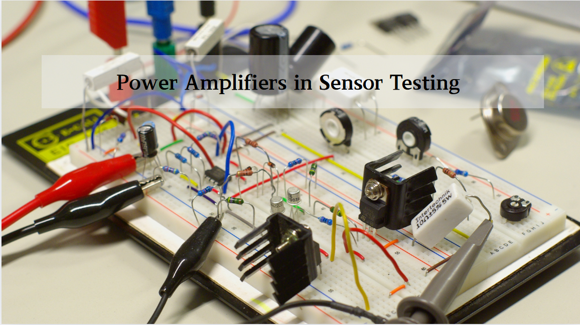
Multivariate Application Analysis of Power Amplifiers in Sensor Testing
In the field of modern sensor testing, power amplifiers (PAs) serve as core components and play an indispensable role. From amplifying weak signals to simulating complex physical environments, power amplifiers provide solid guarantees for the precise testing of sensor performance through their uniqu...
-
2025 / 06 / 28
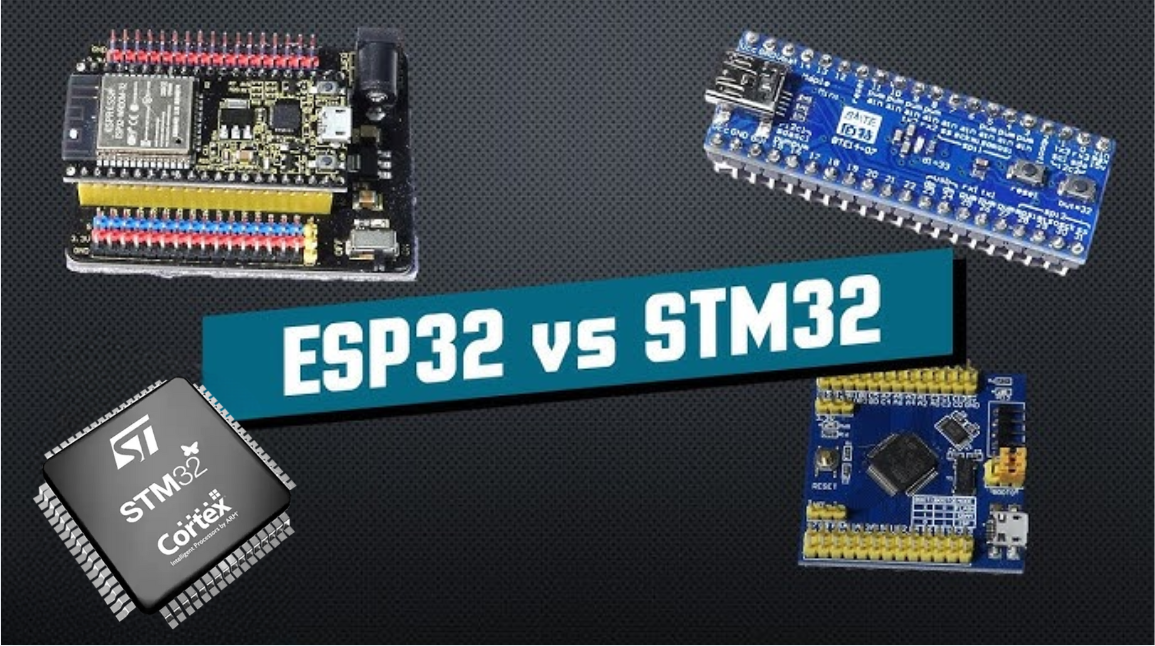
ESP32 vs STM32: Which Microcontroller Suits You Better?
In the field of embedded development, both ESP32 and STM32 are highly favored microcontrollers, each with unique features and advantages. When facing project development, how do you choose between them? This requires comprehensive consideration of multiple factors. The following detailed comparison ...
-
2025 / 06 / 26
Key Strategies to Enhance Buck Power Supply Efficiency
Improving the efficiency of Buck (step-down) switching power supplies requires a multi-dimensional approach targeting energy loss sources, including component selection, topology optimization, control strategies, and thermal management. Below are core strategies and engineering practices:...
-
2025 / 06 / 26
P-Channel MOSFET Turn-On Conditions
The turn-on conditions for a P-channel MOSFET (PMOS) are inverse to those of an N-channel MOSFET (NMOS), primarily governed by the relationship between the gate-source voltage (VGS) and the threshold voltage (Vth), along with voltage polarity. Here are the key points:A PMOS turns on when its gate vo...
-
2025 / 06 / 24
A8304SESTR-T Allegro MicroSystems-Single LNB Supply and Control Voltage Regulator
The Allegro MicroSystems A8304SESTR-T is a single-channel Low Noise Block Regulator (LNBR). It integrates a monolithic boost converter with MOSFET, current sensing, and compensation. Featuring a 704 kHz switching frequency, it uses few external components. With an I²C-compatible interface, it offers...
-
2025 / 06 / 20
EG25GGC-128-SGNS by Quectel Wireless Solutions Co., Ltd: Features,Symbol,Footprint and Datasheet
The Quectel EG25GGC - 128 - SGNS is an LTE Cat 4 module optimized for M2M and IoT. Supporting 3GPP Rel. 11, it offers up to 150Mbps downlink and 50Mbps uplink. With global LTE/UMTS/GSM coverage, it's backward - compatible with EDGE/GPRS. Featuring multi - constellation GNSS (GPS, GLONASS, BeiDou, et...

-
2025 / 06 / 17
STMicroelectronics STM32F413CGU6 Microcontroller: Datasheet, Performance, Features
The STMicroelectronics STM32F413CGU6 is an Arm® Cortex®-M4 based MCU with FPU, operating at up to 100 MHz for 125 DMIPS performance. It features 1MB Flash, 320KB SRAM, and interfaces like USB OTG FS, 3 CAN, ADC, 2 DAC, and multiple serial ports. With low-power modes (Sleep, Stop, Standby), it suits ...
-
2025 / 06 / 13
STMicroelectronics STM32F446ZCT6 -Microcontrollers: A Comprehensive Guide
The STMicroelectronics STM32F446ZCT6 is an ARM Cortex-M4-based MCU with FPU, running at up to 180 MHz. It features 256 KB Flash, 128 KB SRAM + 4 KB backup SRAM, and offers rich peripherals: USB OTG HS/FS, 2 CAN, 3 ADCs, 17 timers, and 20 communication interfaces. In LQFP144 package, industrial temp ...

-
2025 / 06 / 09
MC33887PNB NXP Semiconductors-Motor Drivers:A Comprehensive Guide
The NXP Semiconductors MC33887PNB is a 5.0 A H - bridge power IC with integrated load current feedback. It operates across a 5.0 V - 28 V voltage range, features low RDS(on) (120 mΩ typical), and supports up to 10 kHz PWM. With functions like active current limiting and fault reporting, it ensures r...
-
2025 / 06 / 07
A 16-bit Bus Transceiver: Why Choose the Texas Instruments SN74ACT16245QDLREP?
The Texas Instruments SN74ACT16245QDLREP is a high-performance 16-bit bus transceiver. Designed for harsh industrial and automotive environments, it operates reliably from -40°C to +125°C. With its dual 8-bit non-inverting 3-state architecture, it enables efficient bidirectional data transfer. It of...

2000+
Daily average RFQ Volume

30,000,000
Standard Product Unit

2800+
Worldwide Manufacturers

15,000 m2
In-stock Warehouse
 Wishlist (0 Items)