

- RFQ
- BOM
-
Contact Us
Tel: +86-0755-83501315
Email: sales@sic-components.com


- Chinese
- English
- French
- German
- Portuguese
- Spanish
- Russian
- Japanese
- Korean
- Arabic
- Irish
- Greek
- Turkish
- Italian
- Danish
- Romanian
- Indonesian
- Czech
- Afrikaans
- Swedish
- Polish
- Basque
- Catalan
- Esperanto
- Hindi
- Lao
- Albanian
- Amharic
- Armenian
- Azerbaijani
- Belarusian
- Bengali
- Bosnian
- Bulgarian
- Cebuano
- Chichewa
- Corsican
- Croatian
- Dutch
- Estonian
- Filipino
- Finnish
- Frisian
- Galician
- Georgian
- Gujarati
- Haitian
- Hausa
- Hawaiian
- Hebrew
- Hmong
- Hungarian
- Icelandic
- Igbo
- Javanese
- Kannada
- Kazakh
- Khmer
- Kurdish
- Kyrgyz
- Latin
- Latvian
- Lithuanian
- Luxembou..
- Macedonian
- Malagasy
- Malay
- Malayalam
- Maltese
- Maori
- Marathi
- Mongolian
- Burmese
- Nepali
- Norwegian
- Pashto
- Persian
- Punjabi
- Serbian
- Sesotho
- Sinhala
- Slovak
- Slovenian
- Somali
- Samoan
- Scots Gaelic
- Shona
- Sindhi
- Sundanese
- Swahili
- Tajik
- Tamil
- Telugu
- Thai
- Ukrainian
- Urdu
- Uzbek
- Vietnamese
- Welsh
- Xhosa
- Yiddish
- Yoruba
- Zulu
- Kinyarwanda
- Tatar
- Oriya
- Turkmen
- Uyghur
SMD VS SMT VS THT: WHAT IS BEST FOR MANUFACTURING?
In the ever-evolving landscape of electronics manufacturing, two terms frequently come to the forefront: Surface Mount Technology (SMT) and Surface Mount Devices (SMDs). While they are closely intertwined, understanding the distinctions between them is crucial for professionals and enthusiasts alike in the electronics industry.
SMT: The Assembly Process
Definition and Basics
Surface Mount Technology, or SMT, is a comprehensive method used for assembling electronic components onto a Printed Circuit Board (PCB). It represents a significant shift from the traditional Through-Hole Technology (THT) and has become the dominant approach in modern electronics manufacturing. At its core, SMT involves mounting components directly onto the surface of the PCB rather than inserting them through holes.
The Assembly Steps
Solder Paste Printing: The process begins with applying a precise layer of solder paste onto the designated pads on the PCB. The solder paste is a mixture of tiny solder particles and a flux, which helps in the soldering process. Specialized stencils are used to ensure accurate placement and thickness of the paste. The stencils are designed with openings corresponding to the locations of the component pads on the PCB.
Component Placement: Next, Surface Mount Devices (SMDs) are placed onto the PCB. This is typically done using automated pick-and-place machines. These machines are highly precise and can handle a wide variety of component sizes and shapes. They pick up individual components from reels or trays and accurately position them onto the PCB, aligning them with the solder paste.
Reflow Soldering: After the components are placed, the PCB is passed through a reflow oven. Inside the oven, the temperature is carefully controlled to follow a specific profile. As the temperature rises, the solder paste melts, wetting the component leads and the PCB pads. When the assembly cools down, the solder solidifies, creating a strong mechanical and electrical connection between the components and the PCB.
Advantages of SMT
Higher Component Density: SMT allows for a much greater number of components to be packed onto a single PCB. Since components are mounted on the surface, both sides of the PCB can be utilized, enabling the creation of smaller and more compact electronic devices.
Automation: The assembly process is highly automated, leading to increased production efficiency and consistency. Automated pick-and-place machines can place components at high speeds with remarkable accuracy, reducing the potential for human error.
Cost Savings: In high-volume production, SMT can be more cost-effective. The reduced need for drilling holes (as in THT) and the ability to use smaller components result in lower material costs. Additionally, the automated nature of the process reduces labor costs.
Improved Electrical Performance: SMT components generally have shorter leads, which reduces parasitic inductance and capacitance. This makes SMT suitable for high-frequency applications, where signal integrity is crucial.
Disadvantages of SMT
Complexity in Repairs: Due to the small size of the components and the densely packed nature of SMT assemblies, repairs can be challenging. Specialized equipment and skills are required to desolder and replace faulty components.
Sensitivity to Thermal and Mechanical Stress: SMT solder joints are relatively small and may be more susceptible to damage from thermal cycling and mechanical shock. Care must be taken during the manufacturing process and in the end-use environment to ensure the reliability of the assembly.
SMDs: The Components Themselves
Definition and Characteristics
Surface Mount Devices, or SMDs, are the individual electronic components designed to be mounted directly onto the surface of a PCB using SMT. These components come in a wide variety of forms, including resistors, capacitors, transistors, diodes, integrated circuits (ICs), and more. Unlike through-hole components, SMDs have leads or pads that are soldered directly to the surface of the PCB.
Types of SMDs
Chip Components: These are the simplest form of SMDs and include resistors and capacitors. They are typically rectangular in shape and have metal pads on either end for soldering. Chip resistors and capacitors are available in various sizes, with the most common being specified in imperial (e.g., 0201, 0402) or metric (e.g., 0603, 1005) dimensions. The smaller the size, the more space-efficient they are but also more challenging to handle and assemble.
Small Outline Integrated Circuits (SOICs): SOICs are used for integrated circuits with a relatively small number of pins. They have leads that extend outwards from the sides of the package and are soldered to pads on the PCB. SOICs are commonly used for medium-complexity ICs, such as microcontrollers and logic chips.
Quad Flat Packs (QFPs): QFPs are used for ICs with a larger number of pins. They have leads that extend outwards from all four sides of the package, providing a higher pin count in a relatively small footprint. QFPs are suitable for more complex integrated circuits, such as digital signal processors and some types of memory chips.
Ball Grid Arrays (BGAs): BGAs are a more advanced type of SMD package. Instead of leads, they have an array of solder balls on the bottom of the package. These balls are soldered to corresponding pads on the PCB, providing a large number of electrical connections in a compact space. BGAs are widely used for high-performance ICs, such as microprocessors and graphics processing units (GPUs), where a large number of pins are required.
Advantages of SMDs
Miniaturization: SMDs enable the miniaturization of electronic devices. Their small size allows for the creation of compact and lightweight products, which is highly desirable in today's consumer electronics market.
High-Frequency Performance: As mentioned earlier, the short leads or pads of SMDs result in reduced parasitic effects, making them well-suited for high-frequency applications. This is crucial for technologies such as wireless communication and high-speed data processing.
Cost-Effective in High-Volume: Although SMDs may have a slightly higher unit cost compared to some through-hole components, their use in high-volume production can lead to overall cost savings due to reduced PCB size and more efficient assembly processes.
Disadvantages of SMDs
Handling Challenges: The small size of SMDs makes them difficult to handle manually. Specialized equipment, such as tweezers with fine tips and magnifying glasses, is often required for manual assembly. Additionally, the components are more prone to static electricity damage, so proper ESD (Electrostatic Discharge) precautions must be taken.
Inspection and Testing Complexity: Inspecting and testing SMDs can be more complex due to their small size. Automated optical inspection (AOI) and X-ray inspection are commonly used to detect defects in SMD assemblies, but these methods require specialized equipment and trained operators.
Key Differences Summarized
Conceptual Difference
The most fundamental difference lies in their nature. SMT is a manufacturing process – a set of techniques and steps used to assemble components onto a PCB. It encompasses everything from solder paste application to the final soldering process. On the other hand, SMDs are the physical components that are the subject of this assembly process. They are the building blocks that are placed and soldered using SMT.
Focus of Innovation
Innovation in SMT often centers around improving the assembly process itself. This includes advancements in solder paste formulation, the development of more precise pick-and-place machines, and enhancements to reflow soldering techniques. In contrast, innovation in SMDs is mainly about creating smaller, more powerful, and more efficient components. This involves advancements in semiconductor technology for ICs, improvements in material science for passive components like resistors and capacitors, and the development of new package types to meet the demands of emerging applications.
Impact on Manufacturing
SMT has a significant impact on the overall manufacturing workflow. It determines the layout of the production line, the types of equipment required, and the skills needed by operators. A change in SMT, such as adopting a new soldering process, can require substantial retooling and retraining. SMDs, on the other hand, influence the design of the PCB. The choice of SMDs affects the component placement, the routing of traces on the PCB, and the overall size and shape of the final product.
In conclusion, while Surface Mount Technology (SMT) and Surface Mount Devices (SMDs) are distinct concepts, they are inseparable in the world of electronics manufacturing. SMT provides the means to assemble SMDs onto PCBs, and the continuous evolution of both is driving the electronics industry forward, enabling the creation of smaller, more powerful, and more cost-effective electronic devices. Understanding their differences is essential for optimizing the design, manufacturing, and performance of modern electronics.
https://www.sic-components.com/category-all


Hot Products
View More-
LEDS1-3-26 Essentra Components
-
8900 Keystone Electronics
-
ELM 3-150 Bivar Inc.
-
LEDM-3-18 Essentra Components
-
LEDM-1-28 Essentra Components
-
LEDM-2-15 Essentra Components
-
LEDS2E-8-01 Essentra Components
-

ELM 2-16MM Bivar Inc.
-

ELM 3-245 Bivar Inc.
-
SPC_125 Visual Communications Company - VCC
-
ELM 5-3MM YW Bivar Inc.
-

705820015 Würth Elektronik
Related Blogs
-
2025 / 06 / 30
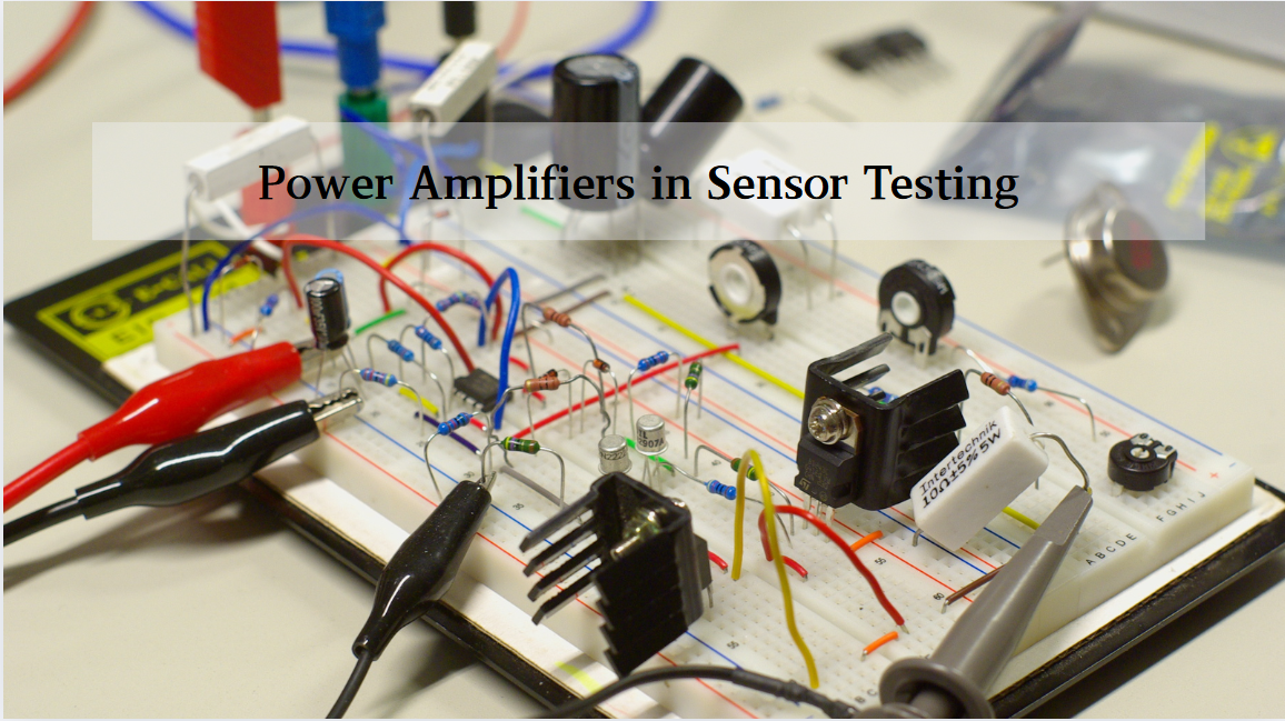
Multivariate Application Analysis of Power Amplifiers in Sensor Testing
In the field of modern sensor testing, power amplifiers (PAs) serve as core components and play an indispensable role. From amplifying weak signals to simulating complex physical environments, power amplifiers provide solid guarantees for the precise testing of sensor performance through their uniqu...
-
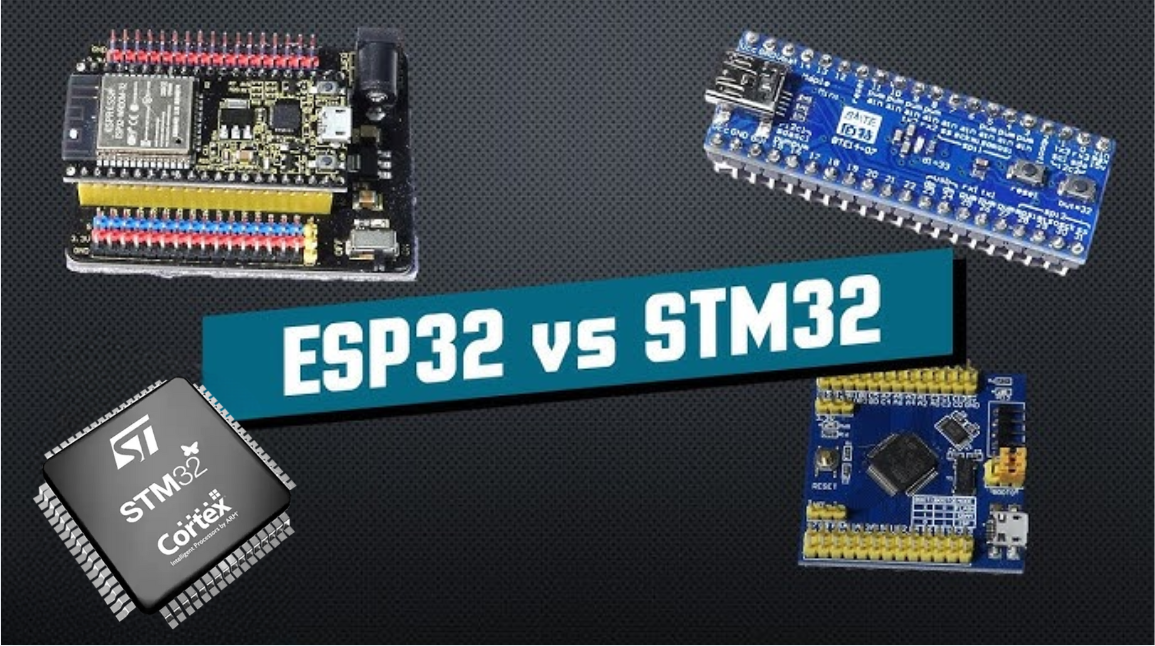
2025 / 06 / 28
ESP32 vs STM32: Which Microcontroller Suits You Better?
In the field of embedded development, both ESP32 and STM32 are highly favored microcontrollers, each with unique features and advantages. When facing project development, how do you choose between them? This requires comprehensive consideration of multiple factors. The following detailed comparison ...
-
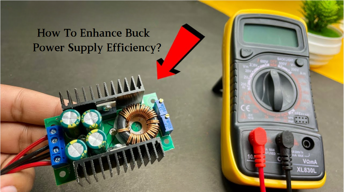
2025 / 06 / 26
Key Strategies to Enhance Buck Power Supply Efficiency
Improving the efficiency of Buck (step-down) switching power supplies requires a multi-dimensional approach targeting energy loss sources, including component selection, topology optimization, control strategies, and thermal management. Below are core strategies and engineering practices:...
-
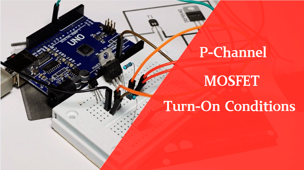
2025 / 06 / 26
P-Channel MOSFET Turn-On Conditions
The turn-on conditions for a P-channel MOSFET (PMOS) are inverse to those of an N-channel MOSFET (NMOS), primarily governed by the relationship between the gate-source voltage (VGS) and the threshold voltage (Vth), along with voltage polarity. Here are the key points:A PMOS turns on when its gate vo...
-
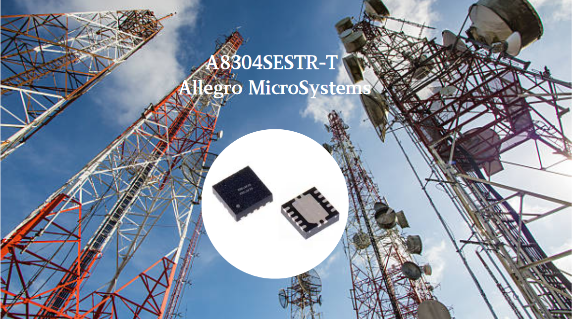
2025 / 06 / 24
A8304SESTR-T Allegro MicroSystems-Single LNB Supply and Control Voltage Regulator
The Allegro MicroSystems A8304SESTR-T is a single-channel Low Noise Block Regulator (LNBR). It integrates a monolithic boost converter with MOSFET, current sensing, and compensation. Featuring a 704 kHz switching frequency, it uses few external components. With an I²C-compatible interface, it offers...
-
2025 / 06 / 20
EG25GGC-128-SGNS by Quectel Wireless Solutions Co., Ltd: Features,Symbol,Footprint and Datasheet
The Quectel EG25GGC - 128 - SGNS is an LTE Cat 4 module optimized for M2M and IoT. Supporting 3GPP Rel. 11, it offers up to 150Mbps downlink and 50Mbps uplink. With global LTE/UMTS/GSM coverage, it's backward - compatible with EDGE/GPRS. Featuring multi - constellation GNSS (GPS, GLONASS, BeiDou, et...

-
2025 / 06 / 17
STMicroelectronics STM32F413CGU6 Microcontroller: Datasheet, Performance, Features
The STMicroelectronics STM32F413CGU6 is an Arm® Cortex®-M4 based MCU with FPU, operating at up to 100 MHz for 125 DMIPS performance. It features 1MB Flash, 320KB SRAM, and interfaces like USB OTG FS, 3 CAN, ADC, 2 DAC, and multiple serial ports. With low-power modes (Sleep, Stop, Standby), it suits ...

-
2025 / 06 / 13
STMicroelectronics STM32F446ZCT6 -Microcontrollers: A Comprehensive Guide
The STMicroelectronics STM32F446ZCT6 is an ARM Cortex-M4-based MCU with FPU, running at up to 180 MHz. It features 256 KB Flash, 128 KB SRAM + 4 KB backup SRAM, and offers rich peripherals: USB OTG HS/FS, 2 CAN, 3 ADCs, 17 timers, and 20 communication interfaces. In LQFP144 package, industrial temp ...

-
2025 / 06 / 09
MC33887PNB NXP Semiconductors-Motor Drivers:A Comprehensive Guide
The NXP Semiconductors MC33887PNB is a 5.0 A H - bridge power IC with integrated load current feedback. It operates across a 5.0 V - 28 V voltage range, features low RDS(on) (120 mΩ typical), and supports up to 10 kHz PWM. With functions like active current limiting and fault reporting, it ensures r...

-
2025 / 06 / 07
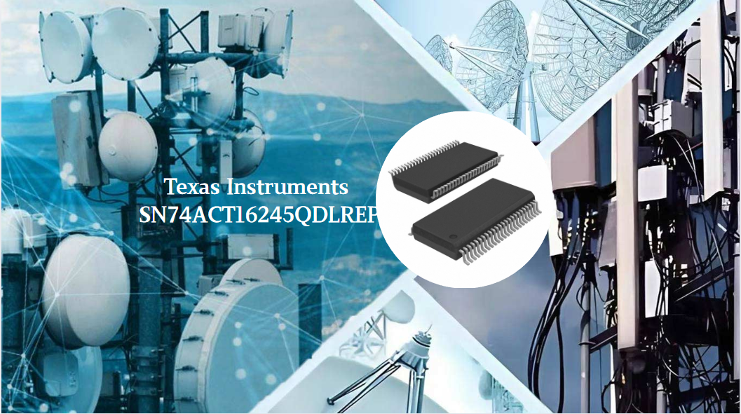
A 16-bit Bus Transceiver: Why Choose the Texas Instruments SN74ACT16245QDLREP?
The Texas Instruments SN74ACT16245QDLREP is a high-performance 16-bit bus transceiver. Designed for harsh industrial and automotive environments, it operates reliably from -40°C to +125°C. With its dual 8-bit non-inverting 3-state architecture, it enables efficient bidirectional data transfer. It of...

2000+
Daily average RFQ Volume

30,000,000
Standard Product Unit

2800+
Worldwide Manufacturers

15,000 m2
In-stock Warehouse
 Wishlist (0 Items)