

- RFQ
- BOM
-
Contact Us
Tel: +86-0755-83501315
Email: sales@sic-components.com


- Chinese
- English
- French
- German
- Portuguese
- Spanish
- Russian
- Japanese
- Korean
- Arabic
- Irish
- Greek
- Turkish
- Italian
- Danish
- Romanian
- Indonesian
- Czech
- Afrikaans
- Swedish
- Polish
- Basque
- Catalan
- Esperanto
- Hindi
- Lao
- Albanian
- Amharic
- Armenian
- Azerbaijani
- Belarusian
- Bengali
- Bosnian
- Bulgarian
- Cebuano
- Chichewa
- Corsican
- Croatian
- Dutch
- Estonian
- Filipino
- Finnish
- Frisian
- Galician
- Georgian
- Gujarati
- Haitian
- Hausa
- Hawaiian
- Hebrew
- Hmong
- Hungarian
- Icelandic
- Igbo
- Javanese
- Kannada
- Kazakh
- Khmer
- Kurdish
- Kyrgyz
- Latin
- Latvian
- Lithuanian
- Luxembou..
- Macedonian
- Malagasy
- Malay
- Malayalam
- Maltese
- Maori
- Marathi
- Mongolian
- Burmese
- Nepali
- Norwegian
- Pashto
- Persian
- Punjabi
- Serbian
- Sesotho
- Sinhala
- Slovak
- Slovenian
- Somali
- Samoan
- Scots Gaelic
- Shona
- Sindhi
- Sundanese
- Swahili
- Tajik
- Tamil
- Telugu
- Thai
- Ukrainian
- Urdu
- Uzbek
- Vietnamese
- Welsh
- Xhosa
- Yiddish
- Yoruba
- Zulu
- Kinyarwanda
- Tatar
- Oriya
- Turkmen
- Uyghur
Packaging and Dimensions of In-Line Resistive Capacitors
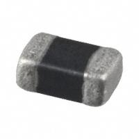
In the circuit system, there is a rich variety of electronic components. Among them, through-hole passive devices, with typical representatives such as resistors and capacitors, exhibit different characteristics in many aspects compared to chip components. Generally, the external dimensions of through-hole passive devices are significantly larger than those of chip components. This is determined by their internal structure and design purposes. The larger size can better adapt to specific working environments and electrical performance requirements.
When manufacturing printed circuit boards (PCBs), the installation process of through-hole devices is relatively complex. Unlike the surface mount method of chip components, through-hole devices require drilling holes in the PCB board so that the pins can pass through and be soldered. This soldering operation has high requirements for the process, and the soldering method is significantly different from that of chip components. It not only requires more precise operating techniques but also incurs relatively higher time and labor costs, so the operation is relatively cumbersome. However, precisely because through-hole resistors and capacitors have a larger physical size, they can withstand higher power loads. Based on this, they are often used in circuits that require larger power output or processing, such as power supply circuits and power amplifier circuits. In these scenarios, through-hole resistors and capacitors can operate stably by virtue of their own characteristics and ensure the normal operation of the circuit.
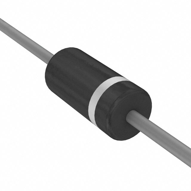
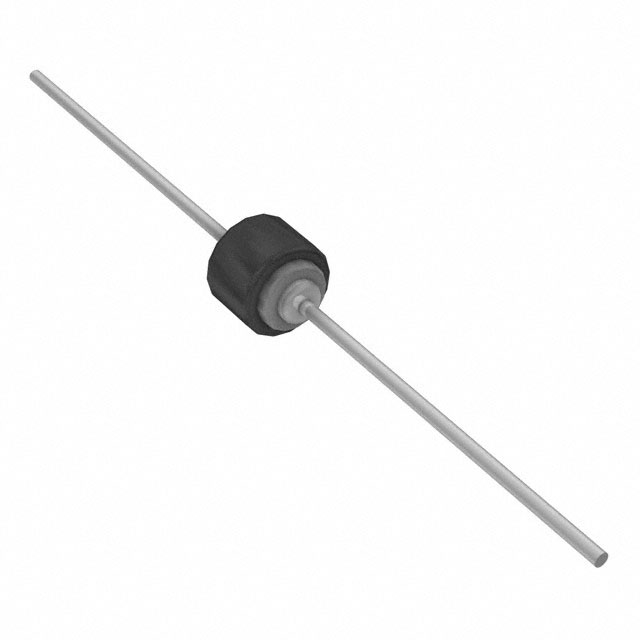
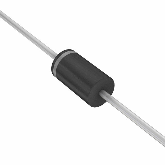
I. Encapsulation and Dimensions of Through-hole Resistors
The encapsulation form of through-hole resistors follows the naming rule of AXIAL-xx, where xx has a specific physical meaning. It represents the distance between the centers of the pads, and the unit of this distance is inches. From the perspective of actual design, the distance between the centers of these pads must be slightly larger than the size of the resistor itself. This design is to ensure that when the resistor is soldered onto the PCB board, there is enough space for the connection and fixation of the pins, and it is also convenient for the smooth progress of the soldering operation. Among common ordinary resistors (that is, resistors with color rings to indicate the resistance value), their encapsulation types include AXIAL-0.3, AXIAL-0.4, AXIAL-0.5, AXIAL-0.6, AXIAL-0.7, AXIAL-0.8, AXIAL-0.9, AXIAL-1.0 and other specifications. Taking the AXIAL-0.3 encapsulation specification as an example, the industry defaults that its pad diameter is 62 mils (mil is a commonly used length unit in the electronics field, that is, mil, 1 mil = 0.0254 mm), and the via diameter is 32 mils. These standardized size settings help to achieve the compatibility and interchangeability of products from different manufacturers during the PCB design and production process.
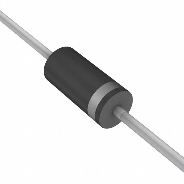
There is a close corresponding relationship between the power parameter of the resistor and the encapsulation size. Through-hole resistors of different power ratings need to be matched with the corresponding encapsulation sizes to meet the requirements of heat dissipation and electrical performance:
For a resistor with a power of 1/8 watt, the AXIAL-0.3 encapsulation is a more suitable choice. This is because the power of 1/8 watt is relatively low, and the heat generated is less. The size of the AXIAL-0.3 encapsulation can effectively dissipate heat while meeting the electrical connection requirements, ensuring that the resistor operates stably within the normal operating temperature range.
For a resistor with a power of 1/4 watt, there is a certain degree of flexibility in the choice of encapsulation. Under normal circumstances, the AXIAL-0.4 encapsulation can be used. However, if in the actual circuit layout, it is necessary to bend the pins of the resistor near the root to adapt to special space requirements, the AXIAL-0.3 encapsulation can also meet its electrical performance and mechanical installation requirements. This is because when the pins are bent near the root, the electrical connection characteristics and heat dissipation situation of the resistor are still well adapted to the AXIAL-0.3 encapsulation.
When the power of the resistor is increased to 1/2 watt, the AXIAL-0.5 encapsulation becomes the main choice. This encapsulation has a larger size and can provide a better heat dissipation surface area to deal with the more heat generated by the resistor at a power of 1/2 watt. However, if the pins are bent near the root during actual installation, the AXIAL-0.4 encapsulation can also meet the usage requirements through reasonable heat dissipation design and electrical layout.
For a resistor with a power of 1 watt, the AXIAL-0.6 encapsulation can generally be selected. This is because the heat generated by the resistor at a power of 1 watt is further increased, and the larger size of the AXIAL-0.6 encapsulation can better dissipate the heat and maintain the stable performance of the resistor. Of course, in the special installation situation where the pins are bent near the root, the AXIAL-0.5 encapsulation can also be used after a strict assessment of the heat dissipation and electrical performance.
For a resistor with a power of 2 watts, the AXIAL-0.8 encapsulation is the standard configuration. A power of 2 watts generates a relatively large amount of heat, and the large-area pads and larger external dimensions of the AXIAL-0.8 encapsulation are helpful for efficient heat dissipation. At the same time, in practical applications, it has been found that the size of AXIAL-0.9 may also be suitable for some specific 2-watt resistors. However, when using the AXIAL-0.9 encapsulation, it is necessary to accurately measure according to the actual size of the specific resistor to ensure the installation accuracy and electrical performance on the PCB board.
For a resistor with a power of 3 watts, the AXIAL-1.0 encapsulation needs to be used. This encapsulation has a large enough space and heat dissipation area, which can effectively deal with the large amount of heat generated by the resistor at a power of 3 watts and ensure the long-term stable operation of the resistor.
When the power of the resistor is as high as 5 watts, the AXIAL-1.2 encapsulation is the best choice. This encapsulation is optimized specifically for 5-watt high-power resistors in terms of size and heat dissipation design, which can ensure that the temperature of the resistor is always within a safe range under high-load working conditions, thus ensuring the stable operation of the entire circuit system.
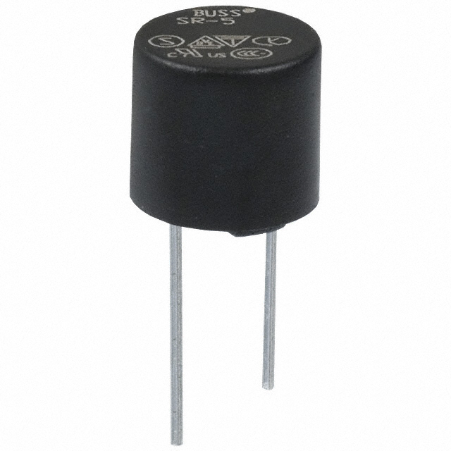
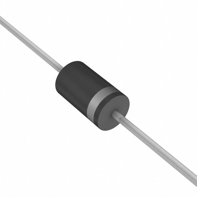
In addition to common ordinary resistors, there are also some special types of resistors, such as thermistors, varistors, photoresistors, and hygroscopic resistors. The appearance and structural design of these special resistors are relatively unique, and sometimes they look very similar to capacitors. Even when first encountered, it is difficult to determine from the appearance that they are resistor components. Given the special appearance of this type of resistor, when designing the PCB encapsulation, the encapsulation method of non-polar capacitors introduced later can be referred to for design. For example, for some small special resistors, encapsulation forms such as RAD-0.2 can be used. By reasonably adjusting the pad size and layout, the stable installation and good electrical connection of the special resistor on the PCB board can be achieved.
In addition, the adjustable resistor, as a special member of the resistor family, has a more unique encapsulation form. Since the adjustable resistor needs to change the resistance value through the adjustment mechanism during use, this requires its pins to have a special structure and installation method. The pins of the adjustable resistor are very different from those of ordinary resistors in terms of shape, width, etc. The width of the pins of many adjustable resistors cannot adopt the ordinary circular design, but is designed into various special shapes according to the requirements of its adjustment function and mechanical structure. Therefore, when designing the encapsulation of the adjustable resistor, the encapsulation form of the ordinary resistor described above generally cannot be directly applied. Instead, it is necessary to carry out a special encapsulation design according to the specific product manual, taking into account factors such as the pin structure, adjustment method, and installation position in the circuit, to ensure that the adjustable resistor can not only achieve the flexible adjustment function of the resistance value on the PCB board but also ensure good electrical performance and mechanical stability.
II. Encapsulation and Dimensions of Through-hole Capacitors
In the classification system of capacitors, common capacitors are mainly divided into two categories: non-polar capacitors and polar capacitors. These two types of capacitors have significant differences in structure, electrical performance, and application scenarios.
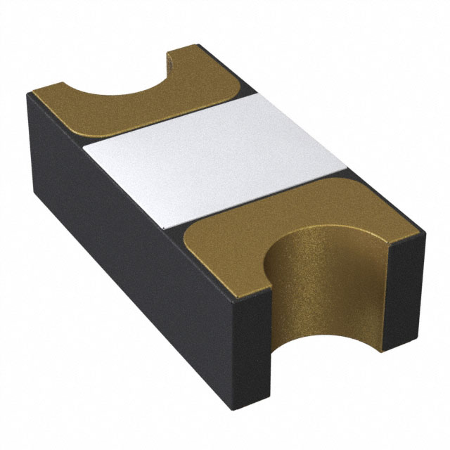
Non-polar Capacitors
Non-polar capacitors use the RAD series for encapsulation identification. Common types include RAD-0.1, RAD-0.2, RAD-0.3, RAD-0.4, etc. The number following RAD here has a clear physical meaning. It represents the distance between the center holes of the pads. This distance parameter is crucial in PCB design. It directly determines the installation position and layout method of the non-polar capacitor on the PCB board. Different RAD models correspond to different distances between the center holes of the pads. Designers need to reasonably select the encapsulation model of the non-polar capacitor according to factors such as the actual size of the capacitor, the requirements of the circuit layout, and the compatibility with other components, to ensure that the design of the entire PCB board is compact, reasonable, and has excellent electrical performance.
Polar Capacitors
Polar capacitors usually refer to electrolytic capacitors, which are widely used in electronic circuits. Among them, there is an electrolytic capacitor with a grayish-white appearance, that is, the so-called solid-state capacitor. In many electronic devices such as motherboards, solid-state capacitors are favored because of their relatively good stability. Solid-state capacitors are different from traditional liquid electrolytic capacitors in internal structure and materials, which makes them exhibit better stability and reliability in electrical performance. Especially in relatively harsh working environments such as high frequency and high temperature, solid-state capacitors can maintain a more stable capacitance value and a lower equivalent series resistance, thereby improving the performance of the entire circuit system.
The encapsulation identification of electrolytic capacitors uses the RB series. Common encapsulation models include RB.2/.4, RB.3/.6, RB.4/.8, RB.5/1.0, etc. In the encapsulation identification of the RB series, the number in front of the symbol represents the interval between the center holes of the pads, and the number behind represents the peripheral size (here, the peripheral size mainly refers to the size range used for silk screen printing identification), and the unit is inches. These size parameters not only determine the installation holes and soldering areas of the electrolytic capacitor on the PCB board but also have a close relationship with factors such as the external dimensions, capacitance value, and electrical performance of the electrolytic capacitor. When designing the PCB, designers need to comprehensively consider various parameters of the electrolytic capacitor, including capacitance value, withstand voltage value, operating temperature range, etc., and at the same time, combine the layout space of the PCB board and the requirements of electrical connection to accurately select the appropriate RB encapsulation model to ensure that the electrolytic capacitor can work normally in the circuit and achieve good coordination with other electronic components.
It should be particularly noted that although electrolytic capacitors and solid-state capacitors have standard encapsulation forms in the industry, their height dimensions do not necessarily completely follow the standard values in actual production and application. This is because different manufacturers may adjust the height of the capacitors to a certain extent according to their own process characteristics, material properties, and the special design requirements of the products during the production process. In addition, there are a large number of customized capacitors on the market. These customized capacitors are specially customized according to specific product design requirements in terms of dimensions, capacitance values, electrical performance, etc. Therefore, in the actual circuit design and product development process, for the selection of electrolytic capacitors, solid-state capacitors, and customized capacitors, it is necessary to closely combine the specific design situation of the product, comprehensively consider various factors, and conduct a comprehensive and detailed evaluation and selection to ensure that the selected capacitors can fully meet the performance requirements of the product and the needs of the actual use scenario.
https://www.sic-components.com/capacitors
Hot Products
View More-
MR2535L onsemi
-
1.5KE200A Taiwan Semiconductor Corporation
-
AVRL101A6R8GTA TDK Corporation
-
MF-ASML020/6-2 Bourns Inc.
-

B72205S0321K211 EPCOS - TDK Electronics
-
0297003.WXNV Littelfuse Inc.
-
TA45-ABFRH050C0-AZM13 SCHURTER Inc.
-
1.5KE82AHE3_B/C Vishay General Semiconductor - Diodes Division
-
SMA6J130CA-TR STMicroelectronics
-
SMAJ54AHM3/I Vishay General Semiconductor - Diodes Division
-
CELHPK11-1-59-150.-A-01-V Sensata-Airpax
-
SPD200220Y2K Tripp Lite
Related Blogs
-
2025 / 06 / 30
Multivariate Application Analysis of Power Amplifiers in Sensor Testing
In the field of modern sensor testing, power amplifiers (PAs) serve as core components and play an indispensable role. From amplifying weak signals to simulating complex physical environments, power amplifiers provide solid guarantees for the precise testing of sensor performance through their uniqu...
-
2025 / 06 / 28
ESP32 vs STM32: Which Microcontroller Suits You Better?
In the field of embedded development, both ESP32 and STM32 are highly favored microcontrollers, each with unique features and advantages. When facing project development, how do you choose between them? This requires comprehensive consideration of multiple factors. The following detailed comparison ...
-
2025 / 06 / 26
Key Strategies to Enhance Buck Power Supply Efficiency
Improving the efficiency of Buck (step-down) switching power supplies requires a multi-dimensional approach targeting energy loss sources, including component selection, topology optimization, control strategies, and thermal management. Below are core strategies and engineering practices:...
-
2025 / 06 / 26
P-Channel MOSFET Turn-On Conditions
The turn-on conditions for a P-channel MOSFET (PMOS) are inverse to those of an N-channel MOSFET (NMOS), primarily governed by the relationship between the gate-source voltage (VGS) and the threshold voltage (Vth), along with voltage polarity. Here are the key points:A PMOS turns on when its gate vo...
-
2025 / 06 / 24
A8304SESTR-T Allegro MicroSystems-Single LNB Supply and Control Voltage Regulator
The Allegro MicroSystems A8304SESTR-T is a single-channel Low Noise Block Regulator (LNBR). It integrates a monolithic boost converter with MOSFET, current sensing, and compensation. Featuring a 704 kHz switching frequency, it uses few external components. With an I²C-compatible interface, it offers...
-
2025 / 06 / 20
EG25GGC-128-SGNS by Quectel Wireless Solutions Co., Ltd: Features,Symbol,Footprint and Datasheet
The Quectel EG25GGC - 128 - SGNS is an LTE Cat 4 module optimized for M2M and IoT. Supporting 3GPP Rel. 11, it offers up to 150Mbps downlink and 50Mbps uplink. With global LTE/UMTS/GSM coverage, it's backward - compatible with EDGE/GPRS. Featuring multi - constellation GNSS (GPS, GLONASS, BeiDou, et...

-
2025 / 06 / 17
STMicroelectronics STM32F413CGU6 Microcontroller: Datasheet, Performance, Features
The STMicroelectronics STM32F413CGU6 is an Arm® Cortex®-M4 based MCU with FPU, operating at up to 100 MHz for 125 DMIPS performance. It features 1MB Flash, 320KB SRAM, and interfaces like USB OTG FS, 3 CAN, ADC, 2 DAC, and multiple serial ports. With low-power modes (Sleep, Stop, Standby), it suits ...

-
2025 / 06 / 13
STMicroelectronics STM32F446ZCT6 -Microcontrollers: A Comprehensive Guide
The STMicroelectronics STM32F446ZCT6 is an ARM Cortex-M4-based MCU with FPU, running at up to 180 MHz. It features 256 KB Flash, 128 KB SRAM + 4 KB backup SRAM, and offers rich peripherals: USB OTG HS/FS, 2 CAN, 3 ADCs, 17 timers, and 20 communication interfaces. In LQFP144 package, industrial temp ...

-
2025 / 06 / 09
MC33887PNB NXP Semiconductors-Motor Drivers:A Comprehensive Guide
The NXP Semiconductors MC33887PNB is a 5.0 A H - bridge power IC with integrated load current feedback. It operates across a 5.0 V - 28 V voltage range, features low RDS(on) (120 mΩ typical), and supports up to 10 kHz PWM. With functions like active current limiting and fault reporting, it ensures r...

-
2025 / 06 / 07
A 16-bit Bus Transceiver: Why Choose the Texas Instruments SN74ACT16245QDLREP?
The Texas Instruments SN74ACT16245QDLREP is a high-performance 16-bit bus transceiver. Designed for harsh industrial and automotive environments, it operates reliably from -40°C to +125°C. With its dual 8-bit non-inverting 3-state architecture, it enables efficient bidirectional data transfer. It of...

2000+
Daily average RFQ Volume

30,000,000
Standard Product Unit

2800+
Worldwide Manufacturers

15,000 m2
In-stock Warehouse
 Wishlist (0 Items)