

- RFQ
- BOM
-
Contact Us
Tel: +86-0755-83501315
Email: sales@sic-components.com


- Chinese
- English
- French
- German
- Portuguese
- Spanish
- Russian
- Japanese
- Korean
- Arabic
- Irish
- Greek
- Turkish
- Italian
- Danish
- Romanian
- Indonesian
- Czech
- Afrikaans
- Swedish
- Polish
- Basque
- Catalan
- Esperanto
- Hindi
- Lao
- Albanian
- Amharic
- Armenian
- Azerbaijani
- Belarusian
- Bengali
- Bosnian
- Bulgarian
- Cebuano
- Chichewa
- Corsican
- Croatian
- Dutch
- Estonian
- Filipino
- Finnish
- Frisian
- Galician
- Georgian
- Gujarati
- Haitian
- Hausa
- Hawaiian
- Hebrew
- Hmong
- Hungarian
- Icelandic
- Igbo
- Javanese
- Kannada
- Kazakh
- Khmer
- Kurdish
- Kyrgyz
- Latin
- Latvian
- Lithuanian
- Luxembou..
- Macedonian
- Malagasy
- Malay
- Malayalam
- Maltese
- Maori
- Marathi
- Mongolian
- Burmese
- Nepali
- Norwegian
- Pashto
- Persian
- Punjabi
- Serbian
- Sesotho
- Sinhala
- Slovak
- Slovenian
- Somali
- Samoan
- Scots Gaelic
- Shona
- Sindhi
- Sundanese
- Swahili
- Tajik
- Tamil
- Telugu
- Thai
- Ukrainian
- Urdu
- Uzbek
- Vietnamese
- Welsh
- Xhosa
- Yiddish
- Yoruba
- Zulu
- Kinyarwanda
- Tatar
- Oriya
- Turkmen
- Uyghur
Integrated Circuit Board
1. Introduction
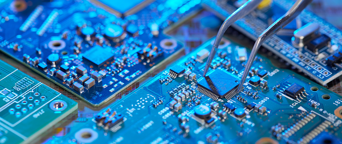
In the fast - paced world of modern technology, integrated circuit boards (IC boards) stand as the unsung heroes that power a vast array of electronic devices. These boards are at the core of everything from the smartphones we carry in our pockets to the complex industrial machinery that drives global production. The integration of multiple electronic components onto a single board has revolutionized the electronics industry, enabling the creation of smaller, more powerful, and more reliable devices. https://www.sic-components.com/development-boards-kits-programmers
2. Definition and Basic Structure https://www.sic-components.com/development-boards-kits-programmers
2.1 What is an Integrated Circuit Board?
An integrated circuit board, also known as a printed circuit board (PCB) when considering the broader context where integrated circuits are mounted, is a flat, rigid board made of an insulating material. Its primary function is to provide a platform for mounting and electrically connecting various electronic components. The most distinguishing feature of an IC board is its ability to host integrated circuits (ICs), which are miniature electronic devices containing a complex network of transistors, resistors, capacitors, and other components fabricated on a single semiconductor chip.
2.2 Substrate Material
The substrate serves as the foundation of the IC board. Common substrate materials include fiberglass - reinforced epoxy (FR - 4), which offers a good balance of mechanical strength, electrical insulation, and cost - effectiveness. In high - performance applications, materials like ceramic substrates may be used. Ceramic substrates provide excellent thermal conductivity and electrical properties, making them suitable for applications where heat dissipation and high - frequency performance are critical, such as in some aerospace and military electronics.
2.3 Conductive Traces
Conductive traces are thin, electrically conductive pathways printed or etched onto the surface of the substrate. These traces are typically made of copper, a highly conductive material. They act as the "wires" of the circuit board, connecting different components together. The width and spacing of the conductive traces are carefully designed based on factors such as the amount of current they need to carry and the signal integrity requirements. In high - speed applications, for example, the traces must be designed to minimize signal attenuation and crosstalk.
2.4 Vias
Vias are small, conductive holes drilled through the substrate. They are used to create electrical connections between different layers of a multi - layer IC board. There are different types of vias, including through - hole vias, which pass through the entire thickness of the board, blind vias, which connect the outer layers to an inner layer, and buried vias, which connect two inner layers without reaching the outer surface. Vias play a crucial role in enabling complex circuit designs by allowing components on different layers to communicate with each other.
2.5 Pads
Pads are small, flat, conductive areas on the surface of the board. They are used to connect components to the conductive traces. Integrated circuits and other discrete components are soldered onto these pads. The size and shape of the pads are designed to match the footprint of the components being mounted, ensuring a reliable electrical and mechanical connection.
3. Types of Integrated Circuit Boards https://www.sic-components.com/development-boards-kits-programmers
3.1 Single - Sided PCBs
Single - sided printed circuit boards have components mounted on only one side of the board, and the conductive traces are also on the same side. This type of board is relatively simple and cost - effective to manufacture. It is commonly used in low - complexity applications where the number of components and connections is limited, such as in some simple consumer electronics like remote controls or small toys.
3.2 Double - Sided PCBs
Double - sided PCBs have components and conductive traces on both sides of the board. This allows for more complex circuit designs compared to single - sided boards. Through - hole vias are used to connect the traces on the two sides. Double - sided PCBs are used in a wide range of applications, from small electronic gadgets to some industrial control boards where a moderate level of complexity is required.
3.3 Multi - Layer PCBs
Multi - layer PCBs consist of multiple layers of conductive traces and insulating materials sandwiched together. These boards can have anywhere from 4 to dozens of layers. The additional layers enable the routing of a large number of signals and power planes, making them suitable for high - density and high - performance applications. For example, in computer motherboards, multi - layer PCBs are used to accommodate the complex interconnections between the CPU, memory, graphics cards, and other components. They are also widely used in telecommunications equipment, where high - speed signal processing and a large number of components need to be integrated.
3.4 Rigid PCBs
Rigid PCBs are made of a stiff, non - flexible material, such as the aforementioned FR - 4. They offer excellent mechanical stability, which is crucial for applications where the board needs to maintain its shape and integrity. Most traditional electronic devices, from desktop computers to household appliances, use rigid PCBs.
3.5 Flexible PCBs
Flexible PCBs are fabricated using flexible materials like polyimide. They can be bent or flexed, making them ideal for applications where space is limited or where the board needs to conform to a non - flat shape. Examples of their use include in smartphones, where flexible PCBs are used to connect different parts of the device, such as the display to the main board, allowing for a more compact and ergonomic design. They are also used in wearable devices, where the ability to bend and conform to the body is essential.
4. Functionality of Integrated Circuit Boards https://www.sic-components.com/development-boards-kits-programmers
4.1 Component Interconnection
The primary function of an IC board is to provide a means of interconnecting various electronic components. By creating a network of conductive traces and vias, the board allows electrical signals to flow between components. For example, in a microcontroller - based system, the IC board connects the microcontroller to other components such as sensors, actuators, memory chips, and communication interfaces. This interconnection enables the transfer of data, control signals, and power, facilitating the overall operation of the system.
4.2 Signal Transmission and Integrity
In high - speed applications, maintaining signal integrity is of utmost importance. As the speed at which signals travel across the board increases, issues such as signal attenuation, reflection, and crosstalk become more pronounced. IC boards are designed with features to mitigate these problems. For instance, the characteristic impedance of the conductive traces is carefully controlled to match the impedance of the components they are connected to. This helps to prevent signal reflections, which can distort the signal and lead to errors in data transmission. In addition, techniques such as differential signaling, where two complementary signals are transmitted on adjacent traces, are used to reduce the effects of noise and interference.
4.3 Power Distribution
IC boards also play a crucial role in distributing power to the various components. Power planes are dedicated layers in multi - layer PCBs that carry the power supply voltages. These planes are designed to provide a stable and low - impedance path for power to reach all the components on the board. Decoupling capacitors are often placed near components to filter out high - frequency noise in the power supply, ensuring that the components receive a clean and stable power source.
4.4 Mechanical Support
Beyond electrical connections, IC boards provide mechanical support for the components. The substrate material holds the components in place, protecting them from physical damage. In some cases, additional mechanical features such as mounting holes or brackets may be incorporated into the board design to further secure the board within the device enclosure.
5. Design and Manufacturing Process https://www.sic-components.com/development-boards-kits-programmers
5.1 Design Phase
5.1.1 Specification Definition
The design process begins with defining the specifications of the IC board. This includes determining the intended application of the board, the types and number of components to be mounted, the required performance parameters (such as signal speed, power consumption, and heat dissipation), and the physical dimensions and form factor of the board. For example, if designing an IC board for a portable medical device, factors such as low power consumption, small size, and high reliability will be key considerations.
5.1.2 Schematic Design
Once the specifications are defined, a schematic diagram of the circuit is created. The schematic shows the electrical connections between all the components in the circuit, using standard symbols to represent each component. This is a crucial step as it serves as the blueprint for the entire design. Designers use computer - aided design (CAD) software to create and edit schematics, which allows for easy modification and error checking.
5.1.3 Layout Design
After the schematic is complete, the layout design phase begins. In this stage, the components are placed on the board, and the conductive traces are routed to connect them. The layout design must take into account both the physical and electrical constraints. Physically, the components need to be placed in a way that maximizes the use of space and allows for easy manufacturing and assembly. Electrically, the trace routing should be optimized to ensure signal integrity, minimize crosstalk, and provide efficient power distribution. CAD software also plays a vital role in this phase, providing tools for automatic component placement and trace routing, which can be further refined by the designer.
5.2 Manufacturing Phase
5.2.1 Substrate Fabrication
The first step in manufacturing an IC board is fabricating the substrate. For rigid PCBs made of FR - 4, the process typically involves laminating layers of fiberglass - impregnated epoxy resin together under high pressure and temperature. The copper layers for the conductive traces are then bonded to the substrate. In the case of flexible PCBs, the polyimide film is coated with a layer of copper. Holes for vias are drilled or laser - ablated in the substrate at this stage.
5.2.2 Circuit Pattern Etching
After the substrate is prepared, the circuit pattern is transferred onto the copper layers. This is usually done using photolithography. A photosensitive material, called photoresist, is applied to the copper - coated substrate. A mask with the desired circuit pattern is then placed over the photoresist, and the board is exposed to ultraviolet light. The areas of the photoresist that are exposed to light change their chemical properties. The unexposed areas of the photoresist are then removed using a developer solution, leaving behind the circuit pattern. The exposed copper is then etched away using a chemical etchant, leaving only the conductive traces in the desired pattern.
5.2.3 Component Assembly
Once the bare board is fabricated, the components are assembled onto it. There are two main methods of component assembly: through - hole and surface - mount technology (SMT). In through - hole assembly, components with leads are inserted through holes in the board and soldered on the other side. This method is more suitable for components that require a more robust mechanical connection or for applications where the components need to be easily replaced. SMT, on the other hand, is the most common method in modern electronics manufacturing. In SMT, components are directly mounted onto the surface of the board using solder paste. Automated pick - and - place machines are used to accurately place the components on the board, and then the board is passed through a reflow oven, where the solder paste melts, creating a reliable electrical and mechanical connection.
5.2.4 Testing
After component assembly, the IC board undergoes a series of tests to ensure its functionality. Electrical tests are performed to check for open circuits, short circuits, and proper signal transmission. This may involve using automated test equipment (ATE) that can apply electrical stimuli to the board and measure the responses. Functional tests are also carried out to verify that the board performs its intended functions as defined in the design specifications. For example, if the board is part of a communication system, tests will be conducted to ensure that it can transmit and receive data correctly.
6. Applications of Integrated Circuit Boards https://www.sic-components.com/development-boards-kits-programmers
6.1 Consumer Electronics
IC boards are omnipresent in consumer electronics. In smartphones, they integrate components such as the CPU, GPU, memory chips, Wi - Fi and Bluetooth modules, and various sensors (such as accelerometers, gyroscopes, and cameras). The compact size and high - performance capabilities of modern IC boards enable the creation of powerful and feature - rich smartphones. In smart TVs, IC boards are used to process video and audio signals, manage connectivity to external devices (such as HDMI ports), and control the display. Other consumer electronics like laptops, tablets, gaming consoles, and home audio systems also rely heavily on IC boards to function.
6.2 Industrial Automation
In industrial settings, IC boards are used in programmable logic controllers (PLCs), which are the brains of many automated manufacturing processes. PLCs use IC boards to control machinery, such as conveyor belts, robotic arms, and assembly line equipment. They receive input signals from sensors (such as proximity sensors, temperature sensors, and pressure sensors) and use the processing power of the ICs on the board to make decisions and send output signals to actuators (such as motors and valves). IC boards are also used in industrial communication devices, such as Ethernet switches and wireless access points, which are essential for connecting different parts of an industrial network.
6.3 Medical Devices
Medical devices require high levels of reliability and precision, and IC boards play a crucial role in meeting these requirements. In patient monitoring devices, such as electrocardiogram (ECG) machines, blood pressure monitors, and pulse oximeters, IC boards are used to process and analyze physiological signals. In more complex medical equipment like MRI machines and CT scanners, IC boards are involved in tasks such as image processing, data storage, and control of the scanning process. The miniaturization and high - performance capabilities of IC boards have also enabled the development of implantable medical devices, such as pacemakers and cochlear implants.
6.4 Automotive Electronics
The automotive industry has seen a significant increase in the use of electronics in recent years, and IC boards are at the heart of many automotive systems. In modern cars, IC boards are used in engine control units (ECUs), which manage the engine's performance by controlling fuel injection, ignition timing, and other parameters. They are also used in anti - lock braking systems (ABS), airbag control systems, and infotainment systems. The development of electric and hybrid vehicles has further increased the demand for advanced IC boards to manage battery charging, motor control, and vehicle - to - grid communication.
6.5 Aerospace and Defense
In aerospace and defense applications, IC boards must meet stringent requirements for reliability, performance, and resistance to harsh environments. They are used in avionics systems, such as flight control computers, navigation systems, and communication equipment. In military applications, IC boards are used in radar systems, missile guidance systems, and soldier - worn electronics. The use of high - performance materials and advanced manufacturing techniques in aerospace and defense IC boards ensures that they can operate reliably in extreme conditions, such as high altitudes, high temperatures, and high levels of radiation.
7. Future Trends https://www.sic-components.com/development-boards-kits-programmers
7.1 Miniaturization and Higher Integration
As the demand for smaller and more powerful electronic devices continues to grow, the trend towards miniaturization and higher integration of components on IC boards will persist. This will involve packing more transistors and other components onto a single IC, as well as further reducing the size of the overall board. Advanced manufacturing techniques, such as 3D printing for circuit boards and nanoscale fabrication for ICs, may play a role in achieving this.
7.2 High - Speed and High - Frequency Performance
With the increasing adoption of technologies such as 5G communication, high - speed data transfer, and advanced computing, IC boards will need to support higher signal speeds and frequencies. This will require the development of new materials and design techniques to improve signal integrity and reduce losses at these high frequencies.
7.3 Sustainability
There is a growing emphasis on sustainability in the electronics industry, and IC boards are no exception. This includes the use of more environmentally friendly materials in board fabrication, such as recycled or biodegradable substrates, and the development of more energy - efficient manufacturing processes. In addition, efforts are being made to improve the recyclability of IC boards at the end of their life cycle.
7.4 Embedded Intelligence and Edge Computing
The trend towards embedded intelligence and edge computing means that more processing power will be integrated directly onto IC boards. This will enable devices to perform complex tasks locally, without relying solely on cloud computing. For example, in IoT devices, IC boards with embedded AI capabilities will be able to analyze sensor data in real - time, make decisions, and take actions without the need for constant communication with a central server.
SIC Supplier stands out in the integrated circuit board domain. They source boards from top manufacturers, offering diverse options like single - sided, multi - layer, and flexible PCBs. Their inventory includes boards compatible with various applications, from consumer electronics to industrial automation. With SIC Supplier, you get high - quality products, reliable delivery, and technical support for all your integrated circuit board needs.
https://www.sic-components.com/development-boards-kits-programmers

Hot Products
View More-
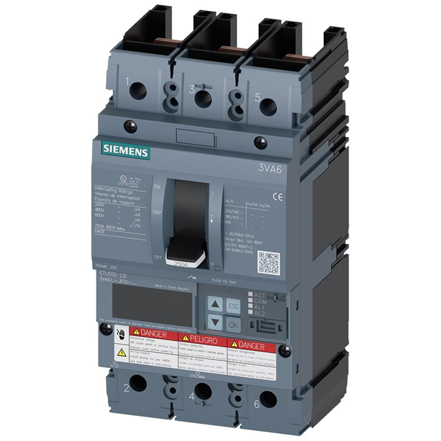
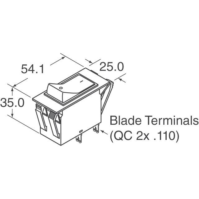
3VA6225-5JP31-0AA0 Siemens
-

IMLK1-1REG4-62-30.0-A-01 Sensata-Airpax
-
APL1-1-60-153 Sensata-Airpax
-
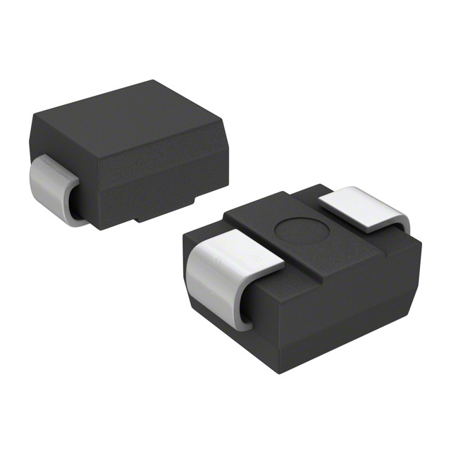
P6SMB130CA-E3/5B Vishay General Semiconductor - Diodes Division
-
NRAS1111-F-0.50A-AA IDEC
-
TPSMP36AHM3/84A Vishay General Semiconductor - Diodes Division
-
IEG1-36034-6-V Sensata-Airpax
-
CA3-B0-26-430-321-D Carling Technologies
-
SMAJ85 Meritek
-
SR-5H-6.3A-AP Eaton - Electronics Division
-
CT2-B2-22-615-522-E Carling Technologies
-
VS8V0UA1LAMTR Rohm Semiconductor
Related Blogs
-
2025 / 06 / 30
Multivariate Application Analysis of Power Amplifiers in Sensor Testing
In the field of modern sensor testing, power amplifiers (PAs) serve as core components and play an indispensable role. From amplifying weak signals to simulating complex physical environments, power amplifiers provide solid guarantees for the precise testing of sensor performance through their uniqu...
-
2025 / 06 / 28
ESP32 vs STM32: Which Microcontroller Suits You Better?
In the field of embedded development, both ESP32 and STM32 are highly favored microcontrollers, each with unique features and advantages. When facing project development, how do you choose between them? This requires comprehensive consideration of multiple factors. The following detailed comparison ...
-
2025 / 06 / 26
Key Strategies to Enhance Buck Power Supply Efficiency
Improving the efficiency of Buck (step-down) switching power supplies requires a multi-dimensional approach targeting energy loss sources, including component selection, topology optimization, control strategies, and thermal management. Below are core strategies and engineering practices:...
-
2025 / 06 / 26
P-Channel MOSFET Turn-On Conditions
The turn-on conditions for a P-channel MOSFET (PMOS) are inverse to those of an N-channel MOSFET (NMOS), primarily governed by the relationship between the gate-source voltage (VGS) and the threshold voltage (Vth), along with voltage polarity. Here are the key points:A PMOS turns on when its gate vo...
-
2025 / 06 / 24
A8304SESTR-T Allegro MicroSystems-Single LNB Supply and Control Voltage Regulator
The Allegro MicroSystems A8304SESTR-T is a single-channel Low Noise Block Regulator (LNBR). It integrates a monolithic boost converter with MOSFET, current sensing, and compensation. Featuring a 704 kHz switching frequency, it uses few external components. With an I²C-compatible interface, it offers...
-
2025 / 06 / 20
EG25GGC-128-SGNS by Quectel Wireless Solutions Co., Ltd: Features,Symbol,Footprint and Datasheet
The Quectel EG25GGC - 128 - SGNS is an LTE Cat 4 module optimized for M2M and IoT. Supporting 3GPP Rel. 11, it offers up to 150Mbps downlink and 50Mbps uplink. With global LTE/UMTS/GSM coverage, it's backward - compatible with EDGE/GPRS. Featuring multi - constellation GNSS (GPS, GLONASS, BeiDou, et...

-
2025 / 06 / 17
STMicroelectronics STM32F413CGU6 Microcontroller: Datasheet, Performance, Features
The STMicroelectronics STM32F413CGU6 is an Arm® Cortex®-M4 based MCU with FPU, operating at up to 100 MHz for 125 DMIPS performance. It features 1MB Flash, 320KB SRAM, and interfaces like USB OTG FS, 3 CAN, ADC, 2 DAC, and multiple serial ports. With low-power modes (Sleep, Stop, Standby), it suits ...
-
2025 / 06 / 13
STMicroelectronics STM32F446ZCT6 -Microcontrollers: A Comprehensive Guide
The STMicroelectronics STM32F446ZCT6 is an ARM Cortex-M4-based MCU with FPU, running at up to 180 MHz. It features 256 KB Flash, 128 KB SRAM + 4 KB backup SRAM, and offers rich peripherals: USB OTG HS/FS, 2 CAN, 3 ADCs, 17 timers, and 20 communication interfaces. In LQFP144 package, industrial temp ...

-
2025 / 06 / 09
MC33887PNB NXP Semiconductors-Motor Drivers:A Comprehensive Guide
The NXP Semiconductors MC33887PNB is a 5.0 A H - bridge power IC with integrated load current feedback. It operates across a 5.0 V - 28 V voltage range, features low RDS(on) (120 mΩ typical), and supports up to 10 kHz PWM. With functions like active current limiting and fault reporting, it ensures r...
-
2025 / 06 / 07
A 16-bit Bus Transceiver: Why Choose the Texas Instruments SN74ACT16245QDLREP?
The Texas Instruments SN74ACT16245QDLREP is a high-performance 16-bit bus transceiver. Designed for harsh industrial and automotive environments, it operates reliably from -40°C to +125°C. With its dual 8-bit non-inverting 3-state architecture, it enables efficient bidirectional data transfer. It of...

2000+
Daily average RFQ Volume

30,000,000
Standard Product Unit

2800+
Worldwide Manufacturers

15,000 m2
In-stock Warehouse
 Wishlist (0 Items)