

- RFQ
- BOM
-
Contact Us
Tel: +86-0755-83501315
Email: sales@sic-components.com


- Chinese
- English
- French
- German
- Portuguese
- Spanish
- Russian
- Japanese
- Korean
- Arabic
- Irish
- Greek
- Turkish
- Italian
- Danish
- Romanian
- Indonesian
- Czech
- Afrikaans
- Swedish
- Polish
- Basque
- Catalan
- Esperanto
- Hindi
- Lao
- Albanian
- Amharic
- Armenian
- Azerbaijani
- Belarusian
- Bengali
- Bosnian
- Bulgarian
- Cebuano
- Chichewa
- Corsican
- Croatian
- Dutch
- Estonian
- Filipino
- Finnish
- Frisian
- Galician
- Georgian
- Gujarati
- Haitian
- Hausa
- Hawaiian
- Hebrew
- Hmong
- Hungarian
- Icelandic
- Igbo
- Javanese
- Kannada
- Kazakh
- Khmer
- Kurdish
- Kyrgyz
- Latin
- Latvian
- Lithuanian
- Luxembou..
- Macedonian
- Malagasy
- Malay
- Malayalam
- Maltese
- Maori
- Marathi
- Mongolian
- Burmese
- Nepali
- Norwegian
- Pashto
- Persian
- Punjabi
- Serbian
- Sesotho
- Sinhala
- Slovak
- Slovenian
- Somali
- Samoan
- Scots Gaelic
- Shona
- Sindhi
- Sundanese
- Swahili
- Tajik
- Tamil
- Telugu
- Thai
- Ukrainian
- Urdu
- Uzbek
- Vietnamese
- Welsh
- Xhosa
- Yiddish
- Yoruba
- Zulu
- Kinyarwanda
- Tatar
- Oriya
- Turkmen
- Uyghur
Inrush Current Limiters (Icl) IC
When electronic devices start up, the current often peaks at several times the rated value—this is known as inrush current. It can cause power supply overload, component damage, or even system failures. The Inrush Current Limiter (ICL) is the core component addressing this issue. As the "safety guardian" during circuit startup, ICL ensures reliable device operation by precisely controlling the current rise rate, widely used in consumer electronics, industrial control, new energy, and other fields. https://www.sic-components.com/inrush-current-limiters-icl
I. Inrush Current: The Invisible Threat During Startup
1. Generation Mechanism of Inrush Current
Capacitor Charging Effect: When power is connected, the initial charging current of energy storage components like filter capacitors and electrolytic capacitors can reach 5-10 times the rated current (e.g., a 100μF capacitor at 5V produces an initial current of 5A).
Inductive Flux Mutation: When inductive loads such as motors and transformers start up, back electromotive force causes sudden current spikes.
Temperature Sensitivity: The on-resistance of power semiconductor devices (e.g., MOSFET) drops sharply at low temperatures, triggering instantaneous high currents.
2. Potential Hazards
Power Supply Impact: Causes input voltage dips, affecting other devices on the same grid.
Component Damage: Fuse burnout, relay contact ablation, and thermal stress failure of semiconductor devices.
System Failure: Repeated inrushes accelerate capacitor aging, reducing device lifespan (statistics show unprotected circuits have a 30% shorter lifespan).
II. Core Principles of ICL: From Current Suppression to Dynamic Regulation
ICL restricts the current rise slope through impedance control or switch timing. The core technical approaches include:
1. Passive Limitation Technology (Passive ICL)
(1) Thermistor Types (NTC/PTC)
NTC (Negative Temperature Coefficient):
Working Principle: High resistance at room temperature (e.g., 10-100Ω) limits current during startup. As current heats the thermistor, resistance drops rapidly (temperature coefficient α > 4%/K), entering a low-resistance steady state.
Advantages: Simple structure, no external power supply, low cost ($0.1-$1).
Limitations: Requires cooling reset after a single inrush (5-30 minutes), unsuitable for high-frequency startups.
Typical Applications: Home appliances (air conditioners, refrigerators), power adapters (limits 5-20A inrush).
PTC (Positive Temperature Coefficient):
Working Principle: Resistance surges (mutation multiple > 100x) above the Curie temperature, limiting continuous overcurrent, and auto-resets after fault removal.
Advantages: Repeatable protection with overload protection.
Limitations: Slower response (millisecond level), unsuitable for ultra-fast inrushes.
(2) Fixed Resistance/Inductance Types
Resistance Voltage Division: Series power resistors (5-50Ω) limit current via Ohm's law (I=V/R), but introduce continuous power consumption (e.g., 10Ω resistor consumes 40W at 2A).
Inductance Filtering: Utilizes inductance to resist current changes (di/dt = L/dV), but large volume (1-10mH inductors reach cm scale), only suitable for low-frequency scenarios.
2. Active Control Technology (Active ICL)
(1) Semiconductor Switch Types
Thyristor (SCR) + Resistance:
SCR is off during startup, with resistance limiting current. In steady state, SCR conducts to short-circuit the resistance, avoiding continuous power consumption (switching completed within 50ms).
Advantages: Low power consumption (steady-state resistance ≈ 0Ω), suitable for high-power scenarios (>100A).
Typical Applications: Industrial frequency converters, photovoltaic inverters (limits 100-500A inrush).
MOSFET Linear Control:
Dynamically adjusts MOSFET gate voltage via MCU, operating the device in the linear region to precisely control current rise rate (di/dt < 10A/μs).
Advantages: Programmable control, supports multiple fast startups.
Limitations: Requires complex drive circuits, higher cost ($5-$10 per channel).
(2) Solid State Relay (SSR)
Utilizes soft-start functions of solid-state devices (e.g., IGBT), gradually increasing conduction via PWM modulation to limit inrush current to 2-3 times the rated value.
III. Comparison of Main ICL Types and Selection Guide
Type Representative Device Response Time Max Limitation Multiple Suitable Scenarios Cost (Single Channel)
NTC Thermistor Murata NTC Series 10-100 ms 5-10x Low-medium power consumer electronics (<10A) $0.1-$1
PTC Thermistor Littelfuse PPTC Series 100 ms-1 s 3-5x Repeatable startup devices (e.g., printers) $0.5-$2
Thyristor + Resistance STMicro STTH8S 50-200 μs 10-20x Industrial power supplies (10-100A) $2-$5
MOSFET Active Infineon OptiMOS 1-10 μs 2-3x High-frequency startup systems (e.g., server power) $5-$15
Four Key Selection Factors
Inrush Parameters:
Peak Current (Ipeak): Maintain a 20% margin (e.g., select 10A rated device for an 8A measured peak).
Duration (Tsurge): NTC suits <50ms short inrushes; active types fit >100ms long durations.
Working Environment:
Temperature Range: Industrial grade requires -40°C~+85°C (e.g., automotive-specific ICL).
Altitude: Derate 5% per 1000m increase for high-altitude scenarios.
System Compatibility:
Interface Form: Through-hole (THD) for high currents; surface-mount (SMD) for miniaturization (e.g., 0603 package: 1.6x0.8mm).
Steady-State Power Consumption: Passive resistive types require P=I²R calculation (e.g., 1Ω resistor consumes 9W at 3A, needing heat dissipation).
Safety Certifications:
Compliance standards: UL1446 (North America), IEC60950 (international); medical devices require ISO13485.
IV. Core Application Scenarios: Universal Startup Protection Needs
1. Consumer Electronics: From Small Appliances to High-End Devices
Mobile Phone Chargers: 5V/3A chargers use 10Ω NTC to limit inrush from 15A to <0.5A.
Laptop Power Supplies: Active MOSFET solutions ensure smooth current rise within 20ms, avoiding adapter overload protection.
2. Industrial Control: Coping with Harsh Startup Environments
Servo Motors: Thyristor ICL limits inrush from 80A to 30A during 220V/5kW motor startup, protecting contactor contacts.
PLC Control Systems: PTC arrays enable independent current limiting for each channel during multi-module power-up, preventing bus voltage collapse.
3. New Energy Field: Critical Barriers for High-Power Scenarios
EV Battery Management Systems (BMS): NTC + relay combinations limit inrush to <50A during battery pack power-up (rated current 200A), protecting circuit boards.
PV Inverters: Active ICL with MCU dynamically adjusts input current during sudden light changes, improving conversion efficiency by 1-3%.
4. Medical Equipment: Prioritizing High Precision and Reliability
MRI Devices: Superconducting magnet power supplies use low-temperature drift NTC (temperature coefficient <0.1%/K) to ensure startup current fluctuations <1%.
Infusion Pumps: PTC devices respond within 0.5s during short circuits, preventing motor overheating and medical accidents.
V. Technological Evolution: From Passive Protection to Intelligent Regulation
1. Material Innovations Driving Performance Breakthroughs
Nano-Composite Thermistor Materials: NTC response speed increases by 50% (e.g., barium titanate-based nanoparticles reduce thermal time constant from 50ms to 20ms).
Silicon Carbide (SiC) MOSFET: Voltage rating increases to 1200V, on-resistance decreases by 30%, suitable for high-voltage EV platforms (800V systems).
2. Trends Toward Intelligence and Integration
Programmable ICL Modules: Integrate MCU and sensors to monitor current waveforms in real time, dynamically adjusting current limiting strategies (e.g., adaptive threshold algorithms).
Multi-Function Integration: Integrated with overvoltage protection (OVP) and overcurrent protection (OCP) to form integrated power protection solutions (e.g., Texas Instruments TPS2490).
3. Green Energy-Saving Design
Low Residual Resistance: NTC steady-state resistance drops below 0.1Ω, reducing long-term power consumption (e.g., <1W at 10A).
Lead-Free Compliance: Meets RoHS 3.0 standards with lead-free solder terminals and eco-friendly packaging.
VI. Challenges and Solutions
1. Heat Dissipation in High-Frequency Startup Scenarios
Solution: Adopt water cooling or high thermal conductivity ceramic packaging (e.g., Al₂O₃ substrate, thermal resistance <5°C/W).
2. Wide Temperature Range Stability
Technology: Introduce temperature compensation algorithms (e.g., active ICL adjusts current limiting thresholds based on real-time temperature).
3. Conflict Between Miniaturization and High Current
Breakthrough: 3D stacking technology (parallel multi-layer NTC) achieves 20A current limiting in a 1210 package.
Conclusion
Although inrush current limiters are seemingly trivial, they carry the critical mission of ensuring safe startup for electronic systems. From early resistance voltage division to today's intelligent dynamic control, ICL evolution has always centered on "higher precision, efficiency, and reliability." Driven by new energy vehicles, Industry 4.0, and other fields, ICL is upgrading from single components to intelligent, integrated solutions, becoming a core technical barrier for long-life device operation. In the future, with breakthroughs in materials science and control algorithms, ICL will play an even more important role in high-voltage, high-frequency scenarios, safeguarding the stable operation of electronic systems.
https://www.sic-components.com/inrush-current-limiters-icl
Hot Products
View More-

009P-253641 Knowles
-
009P-252476 Knowles
-
MESH9.4DAT04WP Seltech
-
680140600218 Dalcomm Tech LLC
-
UAM-P 2010 USound GmbH
-
WAVEGUIDE WG 220 X 150 Visaton GmbH & Co. KG
-
5300-253069 Knowles
-
2800-253591 Knowles
-
X-OVER ARIA LIGHT PC Visaton GmbH & Co. KG
-
KN COILS KN 15,0 MH- 0,5 MM WIRE Visaton GmbH & Co. KG
-
9201-153293 Knowles
-
BF-1860-000 Knowles
Related Blogs
-
2025 / 06 / 30
Multivariate Application Analysis of Power Amplifiers in Sensor Testing
In the field of modern sensor testing, power amplifiers (PAs) serve as core components and play an indispensable role. From amplifying weak signals to simulating complex physical environments, power amplifiers provide solid guarantees for the precise testing of sensor performance through their uniqu...
-
2025 / 06 / 28
ESP32 vs STM32: Which Microcontroller Suits You Better?
In the field of embedded development, both ESP32 and STM32 are highly favored microcontrollers, each with unique features and advantages. When facing project development, how do you choose between them? This requires comprehensive consideration of multiple factors. The following detailed comparison ...
-
2025 / 06 / 26
Key Strategies to Enhance Buck Power Supply Efficiency
Improving the efficiency of Buck (step-down) switching power supplies requires a multi-dimensional approach targeting energy loss sources, including component selection, topology optimization, control strategies, and thermal management. Below are core strategies and engineering practices:...
-
2025 / 06 / 26
P-Channel MOSFET Turn-On Conditions
The turn-on conditions for a P-channel MOSFET (PMOS) are inverse to those of an N-channel MOSFET (NMOS), primarily governed by the relationship between the gate-source voltage (VGS) and the threshold voltage (Vth), along with voltage polarity. Here are the key points:A PMOS turns on when its gate vo...
-
2025 / 06 / 24
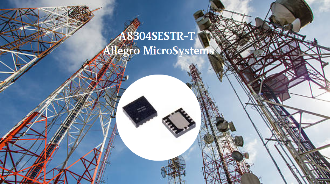
A8304SESTR-T Allegro MicroSystems-Single LNB Supply and Control Voltage Regulator
The Allegro MicroSystems A8304SESTR-T is a single-channel Low Noise Block Regulator (LNBR). It integrates a monolithic boost converter with MOSFET, current sensing, and compensation. Featuring a 704 kHz switching frequency, it uses few external components. With an I²C-compatible interface, it offers...
-
2025 / 06 / 20
EG25GGC-128-SGNS by Quectel Wireless Solutions Co., Ltd: Features,Symbol,Footprint and Datasheet
The Quectel EG25GGC - 128 - SGNS is an LTE Cat 4 module optimized for M2M and IoT. Supporting 3GPP Rel. 11, it offers up to 150Mbps downlink and 50Mbps uplink. With global LTE/UMTS/GSM coverage, it's backward - compatible with EDGE/GPRS. Featuring multi - constellation GNSS (GPS, GLONASS, BeiDou, et...

-
2025 / 06 / 17
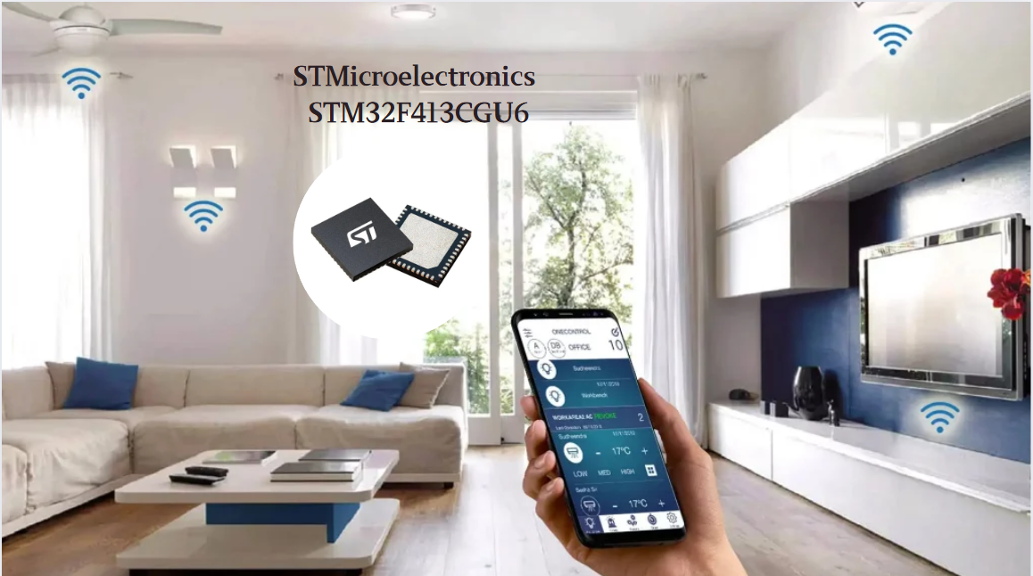
STMicroelectronics STM32F413CGU6 Microcontroller: Datasheet, Performance, Features
The STMicroelectronics STM32F413CGU6 is an Arm® Cortex®-M4 based MCU with FPU, operating at up to 100 MHz for 125 DMIPS performance. It features 1MB Flash, 320KB SRAM, and interfaces like USB OTG FS, 3 CAN, ADC, 2 DAC, and multiple serial ports. With low-power modes (Sleep, Stop, Standby), it suits ...
-
2025 / 06 / 13
STMicroelectronics STM32F446ZCT6 -Microcontrollers: A Comprehensive Guide
The STMicroelectronics STM32F446ZCT6 is an ARM Cortex-M4-based MCU with FPU, running at up to 180 MHz. It features 256 KB Flash, 128 KB SRAM + 4 KB backup SRAM, and offers rich peripherals: USB OTG HS/FS, 2 CAN, 3 ADCs, 17 timers, and 20 communication interfaces. In LQFP144 package, industrial temp ...

-
2025 / 06 / 09
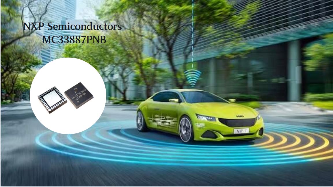
MC33887PNB NXP Semiconductors-Motor Drivers:A Comprehensive Guide
The NXP Semiconductors MC33887PNB is a 5.0 A H - bridge power IC with integrated load current feedback. It operates across a 5.0 V - 28 V voltage range, features low RDS(on) (120 mΩ typical), and supports up to 10 kHz PWM. With functions like active current limiting and fault reporting, it ensures r...
-
2025 / 06 / 07
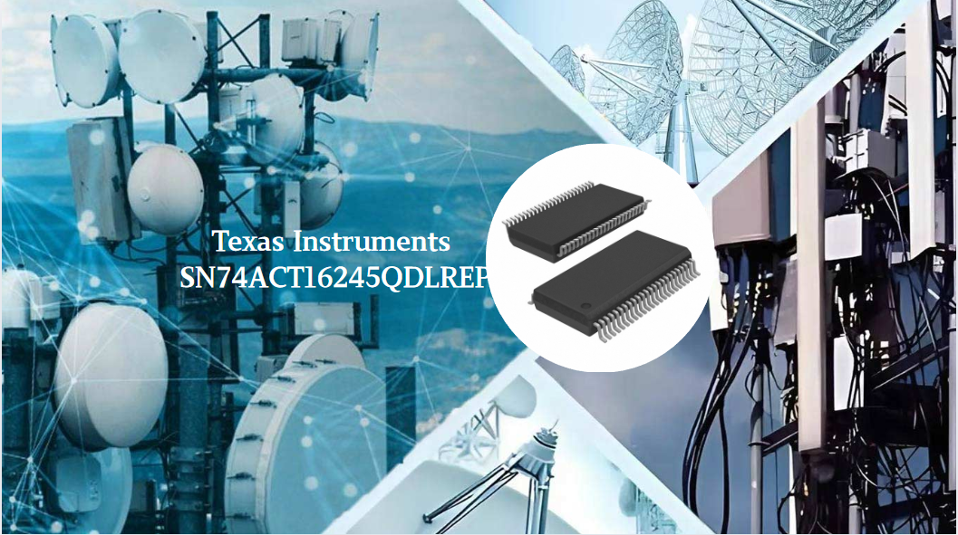
A 16-bit Bus Transceiver: Why Choose the Texas Instruments SN74ACT16245QDLREP?
The Texas Instruments SN74ACT16245QDLREP is a high-performance 16-bit bus transceiver. Designed for harsh industrial and automotive environments, it operates reliably from -40°C to +125°C. With its dual 8-bit non-inverting 3-state architecture, it enables efficient bidirectional data transfer. It of...

2000+
Daily average RFQ Volume

30,000,000
Standard Product Unit

2800+
Worldwide Manufacturers

15,000 m2
In-stock Warehouse
 Wishlist (0 Items)