

- RFQ
- BOM
-
Contact Us
Tel: +86-0755-83501315
Email: sales@sic-components.com


- Chinese
- English
- French
- German
- Portuguese
- Spanish
- Russian
- Japanese
- Korean
- Arabic
- Irish
- Greek
- Turkish
- Italian
- Danish
- Romanian
- Indonesian
- Czech
- Afrikaans
- Swedish
- Polish
- Basque
- Catalan
- Esperanto
- Hindi
- Lao
- Albanian
- Amharic
- Armenian
- Azerbaijani
- Belarusian
- Bengali
- Bosnian
- Bulgarian
- Cebuano
- Chichewa
- Corsican
- Croatian
- Dutch
- Estonian
- Filipino
- Finnish
- Frisian
- Galician
- Georgian
- Gujarati
- Haitian
- Hausa
- Hawaiian
- Hebrew
- Hmong
- Hungarian
- Icelandic
- Igbo
- Javanese
- Kannada
- Kazakh
- Khmer
- Kurdish
- Kyrgyz
- Latin
- Latvian
- Lithuanian
- Luxembou..
- Macedonian
- Malagasy
- Malay
- Malayalam
- Maltese
- Maori
- Marathi
- Mongolian
- Burmese
- Nepali
- Norwegian
- Pashto
- Persian
- Punjabi
- Serbian
- Sesotho
- Sinhala
- Slovak
- Slovenian
- Somali
- Samoan
- Scots Gaelic
- Shona
- Sindhi
- Sundanese
- Swahili
- Tajik
- Tamil
- Telugu
- Thai
- Ukrainian
- Urdu
- Uzbek
- Vietnamese
- Welsh
- Xhosa
- Yiddish
- Yoruba
- Zulu
- Kinyarwanda
- Tatar
- Oriya
- Turkmen
- Uyghur
Comprehensive guide to electronic connectors
In today's highly digital and intelligent era, electronic devices are ubiquitous, permeating every corner of our lives. From the smartphones and laptops we use daily to the complex and sophisticated industrial automation equipment and aerospace instruments, electronic connectors, as indispensable basic components in electronic systems, serve as invisible bridges. They construct the connection networks within electronic devices and between different devices, ensuring the stable transmission of signals and electricity.
I. Core Functions and Characteristics of Electronic Connectors
The core mission of electronic connectors is to establish electrical connections. They can reliably link different electronic components, devices, or systems, ensuring the stable flow of electric current and the accurate transfer of signals. Their performance directly impacts the operation, reliability, and lifespan of electronic devices. Excellent electrical performance is the foundation of electronic connectors, encompassing low resistance, high insulation, and superior signal integrity. This ensures that there is no significant attenuation or distortion of electric current and signals during transmission. In terms of mechanical performance, connectors must have sufficient strength and durability to withstand repeated plugging and unplugging operations, as well as external environmental factors such as vibration and impact. Environmental adaptability is equally crucial. High - quality electronic connectors should be able to maintain stable operation in harsh environments, including high and low temperatures, humidity, and corrosive conditions.
II. Interpretation of Professional Terminologies in Electronic Connectors
There is a series of professional terminologies in the field of electronic connectors, used to precisely describe their properties and characteristics:
Gender: Gender is used to distinguish mating connectors that match in size, shape, and the number of pins. The male connector (plug) has pins that can be inserted into the female connector (socket). The female connector has socket holes containing terminals connected to wires, cables, or devices. The pins of the male plug are inserted into the female jack or socket to complete the electrical connection.
Keying: Most connectors can only be inserted in a specific orientation. Keying is a special design feature, especially important when multiple pairs of connectors are required. The keyway structure prevents incorrect mating due to wrong angles or incompatible sockets, effectively avoiding mechanical and electrical damage. This is particularly applicable to symmetrical connectors.
Locking Mechanisms: Locking mechanisms secure the connectors in place after mating. They prevent the connectors from shifting or accidentally disconnecting due to collisions or vibrations, thus protecting electronic devices from connection interruptions. Common locking methods include push - pull connectors, bayonet couplings, and fine - thread screw couplings.
Number of Contacts: This refers to the number of pins used to establish electrical connections. The number of contacts can range widely, from 2 to over 200, depending on the model and design requirements of the electrical connector.
Contact Pitch: Contact pitch, measured in millimeters, is the center - to - center distance between adjacent pins. When pins are arranged in an array, the pitch between rows and columns may vary. This parameter directly affects the compatibility of connectors. A larger pitch means fewer terminals per unit area, reducing the risk of electrical arcing (when pins are too close, electric current may jump between them, causing arcing). Therefore, precise calculation of contact pitch is essential during connector assembly.
Pin Numbering: Pin numbering is a method used to identify each pin of an electronic connector. The counting direction is usually from left to right or from bottom to top, depending on the type of connector. This numbering system enables precise wire connections when dealing with multi - pin connectors.
Pin Sequence: The pin sequence determines the order in which pins make contact during the connection process. Typically, ground pins are designed to make contact first, ensuring the normal operation of the device and providing protection. Essentially, it is about prioritizing the connection order of pins.
Mating Cycles: Mating cycles represent the number of times an electronic connector can be connected and disconnected. The mating cycle varies significantly among different types of connectors. For example, USB connectors can withstand thousands of plug - in and unplugging operations, while FFC and FPC connectors have relatively fewer cycles. Factors influencing the mating cycle include connector materials, plating type, pin thickness, pass/fail threshold, and mating style.
Mounting: Mounting refers to the specific methods by which electronic connectors are installed on electrical devices. It mainly includes board - mount, through - hole, surface - mount, edge - mount, panel - mount, and cable - mount. Different mounting methods determine the fixing form and position of the connector on the device.
Termination: Termination is the method of connecting conductive wires to the connector. Commonly used methods include crimping, soldering, or screwing. The stripped wires are attached to the contact points of the connector.
Strain Relief: Strain relief is achieved through specific accessories or sleeves that dissipate external forces acting on the electronic connector. This prevents stress concentration and potential damage to the connector, enhancing its mechanical stability.
III. Classification and Applications of Electronic Connectors
Electronic connectors can be classified according to the interconnection levels into the integrated circuit (IC) chip level, IC to package level, IC package to circuit board level, board - to - board level, wire - to - board or sub - assembly to sub - assembly level, and box - to - box level (connection between systems). In the market, numerous types of electronic connectors have been developed to meet the requirements of different applications and usage environments. Selecting the appropriate connector requires comprehensive consideration of factors such as voltage and current ratings, contact resistance, mating cycles, shielding efficiency, and ingress protection (IP ratings). The following are some common types of connectors and their characteristics:
(I) Circular Connectors
Circular connectors are renowned for their durability and adaptability, characterized by their circular coupling interface. The pins or sockets are arranged in a circular pattern within a cylindrical housing. They offer excellent durability, capable of withstanding extreme temperatures (both high and low), humidity, dust, and mechanical shocks. Their locking mechanisms ensure a secure connection, effectively preventing slippage, signal loss, and disconnection. Moreover, circular connectors come in a wide range of specifications, with various pin forms and materials, making them suitable for handling diverse signal and power requirements. They are widely used in industrial equipment, critical aerospace systems, and military and defense applications in extreme environments.
(II) Rectangular Connectors
Rectangular connectors are widely used in the electronics field due to their flexibility and versatility. With a rectangular shape, these connectors typically have multiple rows of pins arranged in a row or matrix. They feature high density, allowing for a large number of contact points in a small space, which makes them ideal for high - density connection applications. Most rectangular connectors have polarization features to prevent incorrect mating, ensuring proper alignment and protecting both the connector and the equipment. Their robust housing and locking designs make them structurally strong, suitable for challenging application scenarios. They are commonly found in computers and peripherals, telecommunications, and industrial automation.
(III) Coaxial Connectors
Coaxial connectors are specifically designed for transmitting high - frequency electrical signals with minimal signal loss and interference. Their circular structure consists of an inner core, an insulating layer, a braided shield, and an outer jacket. The unique shielded design provides excellent signal integrity, effectively resisting electromagnetic interference (EMI) and radio - frequency interference (RFI), thus ensuring optimal signal quality. They also have high - bandwidth capabilities, enabling the transmission of high - frequency signals and supporting large - volume data transfer. Additionally, their specific impedance values are designed to reduce signal reflection and enhance power transfer efficiency. Coaxial connectors are commonly used in radio - frequency (RF) applications, data transmission, and audio and video fields.
(IV) Other Types of Connectors
D - Sub Connectors: Also known as D - subminiature connectors due to their D - shaped metal shells, they are commonly used for computer interface devices, such as serial and parallel ports, as well as video graphics adapters (VGA).
RJ45 Connectors: Used in Ethernet network cables, they are the most common connectors for connecting computers, routers, and other network devices today. These modular connectors have 8 pins.
USB Connectors: Widely used for connecting various computer peripherals, such as keyboards, mice, printers, flash drives, etc. There are several types, including USB - A, USB - B, USB - C, and Mini - USB.
DIN Connectors: Mostly circular in shape, they are applied in various fields, including audio equipment, automotive systems, and industrial control systems.
Fiber Optic Connectors: Used to connect fiber optic cables that transmit data via light signals, they are widely applied in high - speed data communication and telecommunication systems.
HDMI Connectors: Specifically designed for consumer electronics, they enable the transmission of digital audio and video.
Modular Connectors: Since their introduction in the 1960s, these connectors, also known as RJ connectors, have become indispensable in the fields of telecommunications and data communication.
IV. Installation and Termination of Electronic Connectors
The installation and termination methods of connectors are crucial to their performance and reliability. Installation methods mainly include surface - mount, through - hole, suspension - mount, notch - mount, and through - board mount, which mainly involve the overall connection, fastening, and fixing of the connector to the circuit board. Termination, on the other hand, focuses on establishing the connection at both ends of the connector, that is, the connection between the wire and the connector.
Installation Types: Through - hole pin installation involves connecting the termination leads through holes in the circuit board. Surface - mount installation uses contact pads on the circuit board for connection. Panel - mount, a type of surface - mount, fixes the connector to the panel hole using threads or nuts. Suspension - mount installs the connector on the cable it terminates. Notch - mount places the connector at the edge of the circuit board, using the edge space to reduce the form factor, which is suitable for space - constrained scenarios. Through - board mount combines the features of notch - mount and panel - mount, with some terminals installed through holes and soldered on the same side as the mating connector, while other terminals are surface - mounted on the circuit board side where the connector is installed.
Termination Methods: Through - hole soldering is commonly used for board - to - board and wire - to - board connections. The terminals are inserted into the drilled holes and then soldered to the contact pads on the other side of the circuit board. In surface - mount termination, the terminal leads and mounting pads are on the same side of the circuit board. Components can be manually mounted and then soldered using reflow soldering or wave soldering. Crimping involves pressing wires and cables onto crimp terminals or connector strips. By deforming the wire bundle through compression, a low - resistance electrical connection is formed. Compared with soldering, crimping can avoid problems such as brittleness and cracking of soldered joints, but strict adherence to operating specifications is required. Insulation Displacement Connectors (IDC) have sharp blades that strip the insulation layer when inserted into the wire or cable. Once properly placed, the exposed part of the wire is cold - welded to the connector terminals. IDC is commonly used for ribbon cable connectors, as well as telephone and network plugs. Straight - in termination involves directly pushing the stripped wire into the connector or locking it in place. It is suitable for low - vibration environments, is easy to operate, and can be used as a temporary or permanent termination method.
V. Development Trends of the Electronic Connector Industry
With the vigorous development of emerging technologies such as 5G communication, the Internet of Things, artificial intelligence, and autonomous driving, the electronic connector industry is facing new opportunities and challenges:
Performance Enhancement: The demand for high - speed transmission capabilities of connectors is increasing rapidly. New - generation standards represented by USB4 and Thunderbolt 4 have increased the data transmission rate to 40Gbps or even higher. Meanwhile, power consumption optimization has become an important development direction. Lower power consumption helps extend the battery life of electronic devices and is in line with the concept of environmental protection.
Form Transformation: The trend of miniaturization and micro - miniaturization is becoming more and more prominent. As electronic devices continue to develop towards being thinner, lighter, and more portable, the size of connectors is constantly shrinking. Micro - connectors are increasingly being used in products such as wearable devices and micro - sensors.
Functional Integration: Multi - functional integrated connectors are gradually emerging. These connectors can simultaneously transmit multiple types of signals, such as electricity, data, audio, and video. This reduces the number of interfaces required by devices, simplifies the design and assembly process, and improves the overall reliability and aesthetics of the devices.
Intelligent Evolution: Smart connectors with self - diagnosis and self - adaptation functions are beginning to emerge. These connectors can real - time monitor parameters such as connection status and transmission quality and automatically adjust the working mode according to the actual situation. This improves the stability and reliability of the system and lays the foundation for the development of future intelligent electronic systems.
VI. Conclusion
Electronic connectors, although seemingly unremarkable yet omnipresent electronic components, have become important drivers of the development of the electronics industry with their diverse types and continuously evolving technologies. From daily consumer electronics to cutting - edge technological fields, they have always been the key to ensuring the normal operation of electronic devices. With the rapid advancement of science and technology, electronic connectors will continue to innovate and upgrade to adapt to more complex and diverse electronic application scenarios in the future, and continue to write a glorious chapter in connecting the world.
https://www.sic-components.com/connectors-interconnects

Hot Products
View More-

AT88CK201BK Microchip Technology
-
ST25-TAG-BAG-U STMicroelectronics
-
OM26630FDK NXP USA Inc.
-

OM5597/RD2612,699 NXP USA Inc.
-
TRF7960AEVM Texas Instruments
-
ST25TV02KC-ASEAL STMicroelectronics
-
ADA-FM3-100PMC-RFID-TAG1 Infineon Technologies
-
SL900A-DK-STQFN16 ams-OSRAM USA INC.
-
ATA2270-EK1 Microchip Technology
-
AS3931 DB ams-OSRAM USA INC.
-
AT89C5121-SK1 Microchip Technology
-
0134290004 Molex
Related Blogs
-
2025 / 06 / 30
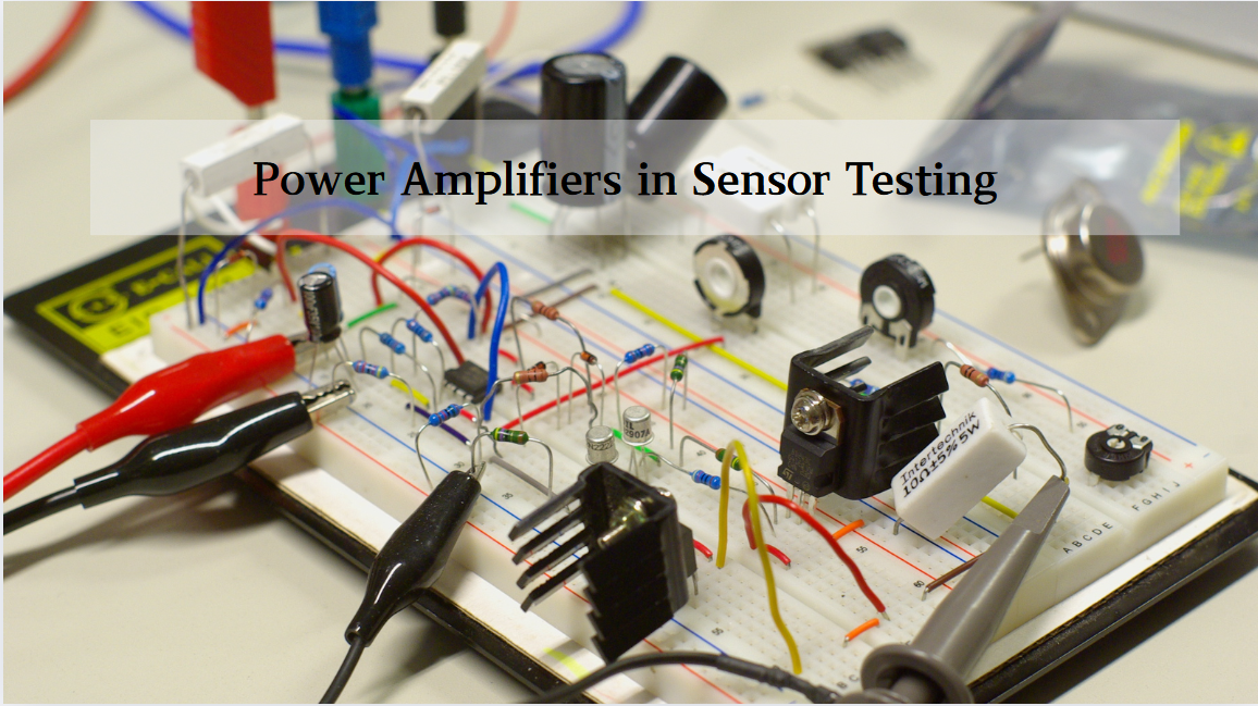
Multivariate Application Analysis of Power Amplifiers in Sensor Testing
In the field of modern sensor testing, power amplifiers (PAs) serve as core components and play an indispensable role. From amplifying weak signals to simulating complex physical environments, power amplifiers provide solid guarantees for the precise testing of sensor performance through their uniqu...
-
2025 / 06 / 28
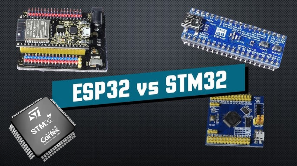
ESP32 vs STM32: Which Microcontroller Suits You Better?
In the field of embedded development, both ESP32 and STM32 are highly favored microcontrollers, each with unique features and advantages. When facing project development, how do you choose between them? This requires comprehensive consideration of multiple factors. The following detailed comparison ...
-
2025 / 06 / 26
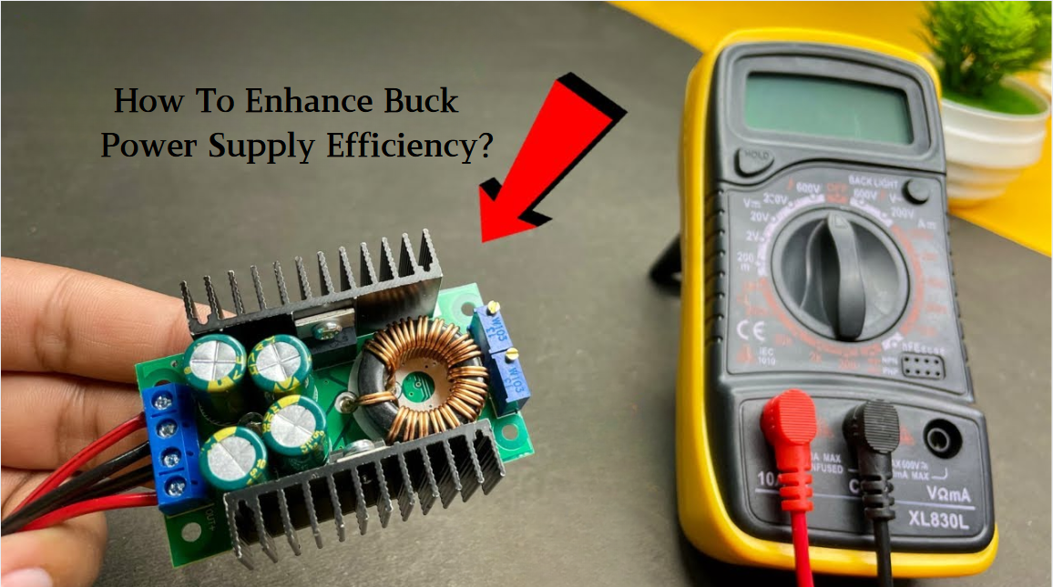
Key Strategies to Enhance Buck Power Supply Efficiency
Improving the efficiency of Buck (step-down) switching power supplies requires a multi-dimensional approach targeting energy loss sources, including component selection, topology optimization, control strategies, and thermal management. Below are core strategies and engineering practices:...
-
2025 / 06 / 26
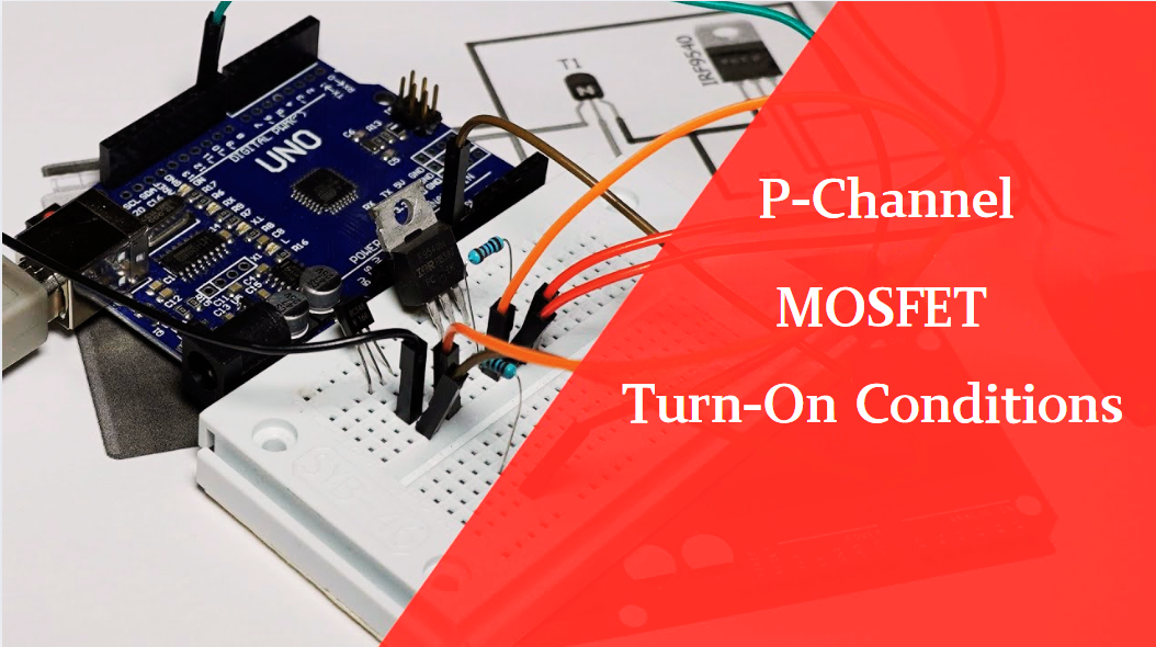
P-Channel MOSFET Turn-On Conditions
The turn-on conditions for a P-channel MOSFET (PMOS) are inverse to those of an N-channel MOSFET (NMOS), primarily governed by the relationship between the gate-source voltage (VGS) and the threshold voltage (Vth), along with voltage polarity. Here are the key points:A PMOS turns on when its gate vo...
-
2025 / 06 / 24
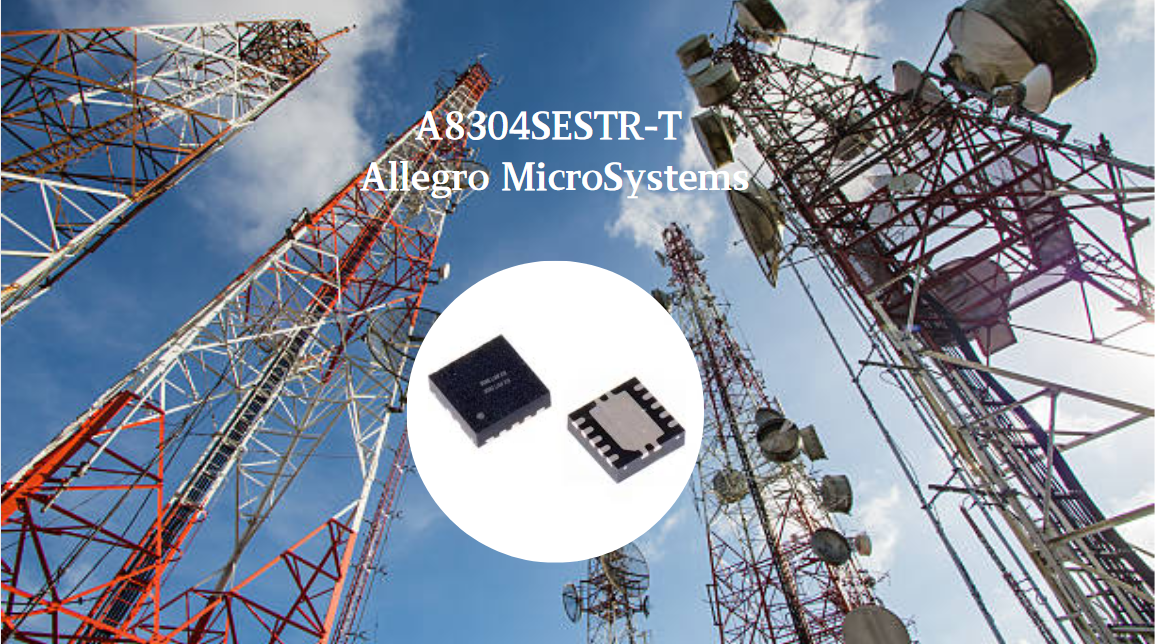
A8304SESTR-T Allegro MicroSystems-Single LNB Supply and Control Voltage Regulator
The Allegro MicroSystems A8304SESTR-T is a single-channel Low Noise Block Regulator (LNBR). It integrates a monolithic boost converter with MOSFET, current sensing, and compensation. Featuring a 704 kHz switching frequency, it uses few external components. With an I²C-compatible interface, it offers...
-
2025 / 06 / 20
EG25GGC-128-SGNS by Quectel Wireless Solutions Co., Ltd: Features,Symbol,Footprint and Datasheet
The Quectel EG25GGC - 128 - SGNS is an LTE Cat 4 module optimized for M2M and IoT. Supporting 3GPP Rel. 11, it offers up to 150Mbps downlink and 50Mbps uplink. With global LTE/UMTS/GSM coverage, it's backward - compatible with EDGE/GPRS. Featuring multi - constellation GNSS (GPS, GLONASS, BeiDou, et...

-
2025 / 06 / 17
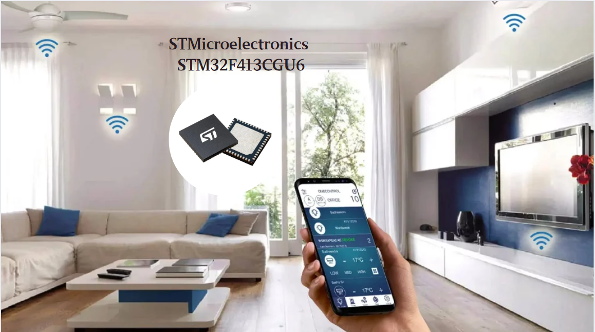
STMicroelectronics STM32F413CGU6 Microcontroller: Datasheet, Performance, Features
The STMicroelectronics STM32F413CGU6 is an Arm® Cortex®-M4 based MCU with FPU, operating at up to 100 MHz for 125 DMIPS performance. It features 1MB Flash, 320KB SRAM, and interfaces like USB OTG FS, 3 CAN, ADC, 2 DAC, and multiple serial ports. With low-power modes (Sleep, Stop, Standby), it suits ...
-
2025 / 06 / 13
STMicroelectronics STM32F446ZCT6 -Microcontrollers: A Comprehensive Guide
The STMicroelectronics STM32F446ZCT6 is an ARM Cortex-M4-based MCU with FPU, running at up to 180 MHz. It features 256 KB Flash, 128 KB SRAM + 4 KB backup SRAM, and offers rich peripherals: USB OTG HS/FS, 2 CAN, 3 ADCs, 17 timers, and 20 communication interfaces. In LQFP144 package, industrial temp ...

-
2025 / 06 / 09
MC33887PNB NXP Semiconductors-Motor Drivers:A Comprehensive Guide
The NXP Semiconductors MC33887PNB is a 5.0 A H - bridge power IC with integrated load current feedback. It operates across a 5.0 V - 28 V voltage range, features low RDS(on) (120 mΩ typical), and supports up to 10 kHz PWM. With functions like active current limiting and fault reporting, it ensures r...
-
2025 / 06 / 07
A 16-bit Bus Transceiver: Why Choose the Texas Instruments SN74ACT16245QDLREP?
The Texas Instruments SN74ACT16245QDLREP is a high-performance 16-bit bus transceiver. Designed for harsh industrial and automotive environments, it operates reliably from -40°C to +125°C. With its dual 8-bit non-inverting 3-state architecture, it enables efficient bidirectional data transfer. It of...

2000+
Daily average RFQ Volume

30,000,000
Standard Product Unit

2800+
Worldwide Manufacturers

15,000 m2
In-stock Warehouse
 Wishlist (0 Items)