LM2576 is a classic step-down switching regulator introduced by Texas Instruments (TI). Since its launch, it has occupied an important position in the field of DC power conversion. With its mature technology, stable performance, and wide applicability, it has become a benchmark product in medium and low-power step-down scenarios. Its application scenarios cover multiple fields such as industrial control, automotive electronics, consumer electronics, and battery-powered devices. Through this article, engineers and electronics enthusiasts can quickly and comprehensively grasp the relevant knowledge of LM2576, providing clear and practical guidance for power supply design work.
Step-Down Voltage Regulator LM2576 Overview
The LM2576 is a classic inductor-based step-down voltage regulator launched by Texas Instruments. Designed specifically for medium and low-power scenarios, it features a maximum output current of 1A and is widely used in industrial control, automotive electronics, and other fields.It has an input voltage range of 7-40V (with some m odels reaching up to 60V) and offers both fixed output voltages (such as 3.3V/5V) and adjustable output voltages (1.23-37V). Operating at a switching frequency of 52kHz, it achieves a conversion efficiency of 75%-88%, boasting significant energy efficiency advantages. The chip integrates overcurrent protection and thermal shutdown functions to enhance system reliability. Its peripheral circuit is simple, requiring only an inductor, capacitor, and diode to operate, resulting in a low design threshold. Packages like TO-220 facilitate heat dissipation and adapt to various installation requirements, making it an optimal choice that balances performance and ease of use.
If your project happens to require a model from this series, please contact us to get the latest quotation.
Step-Down Voltage Regulator LM2576 Pinouts
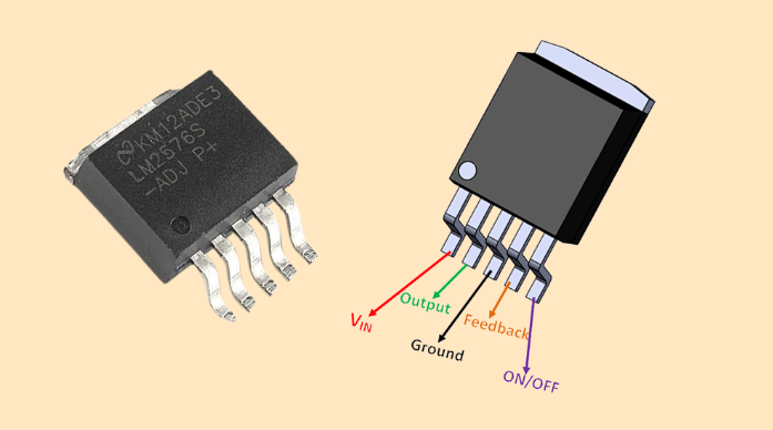
Taking the commonly used TO-220 package (model LM2576T) as an example, the functions of its pins are shown in the table below:
| Pin Number | Pin Name | Function Description |
|---|---|---|
| 1 | Vin | Input voltage pin, connected to the unregulated DC input voltage, which must be within the chip's specified range |
| 2 | Vout | Output voltage pin, providing a stable DC output voltage |
| 3 | GND | Ground pin, providing a reference ground for the chip |
| 4 | Feedback | Feedback pin, used to detect the output voltage and realize closed-loop regulation of the output voltage. For fixed-output models, this pin has a built-in voltage divider network; for adjustable-output models, an external resistor divider network is required |
| 5 | On/Off | Switch control pin, which controls the chip's on/off status through an external signal. When this pin is connected to a low level, the chip turns off; when connected to a high level, the chip works normally (some models may have the opposite logic, so refer to the specific datasheet) |
Pin Characteristics and Design Considerations
Vin pin: The input voltage must be within the specified range (usually 7V-40V); otherwise, it may cause chip damage or abnormal operation. In design, an appropriate filter capacitor should be added at the input end to reduce ripple and noise in the input voltage.
Vout pin: The accuracy of the output voltage is related to the load. In designing the output circuit, components such as inductors and capacitors should be selected reasonably to ensure that the stability and ripple of the output voltage meet the requirements.
Feedback pin: This pin is very sensitive to noise. During wiring, its length should be minimized, and it should avoid crossing with the wiring of the power path to prevent noise interference from affecting the stability of the output voltage. For adjustable-output models, the external resistors should be high-precision resistors (such as 1% tolerance) to ensure the accuracy of the output voltage.
On/Off pin: If remote control of the chip's switch state is not required, this pin can be directly connected to a high level (for high-level enabled models) or left floating (according to the requirements of the specific model).
LM2576 Functional Block Diagram
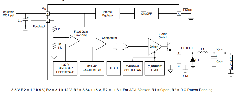
The internal structure of the LM2576 mainly consists of the following core modules:
Voltage reference: Provides a stable reference voltage, serving as the input benchmark for the error amplifier.
Error amplifier: Compares the feedback voltage with the reference voltage, amplifies the error signal between them, and uses it to control the on/off state of the power switch.
Oscillator: Generates a fixed-frequency (52kHz) clock signal to control the switching rhythm of the entire circuit.
Power switch: Typically a MOSFET, which is turned on or off under the control of the clock signal and the output signal of the error amplifier, enabling energy transfer and conversion.
- Protection circuit: Includes overcurrent protection and thermal shutdown circuits to protect the chip under abnormal conditions.
Its working process is as follows: After the input voltage is sampled, a feedback voltage is obtained. This feedback voltage is compared with the reference voltage in the error amplifier to generate an error signal. The error signal is combined with the clock signal generated by the oscillator to control the on/off of the power switch. When the power switch is turned on, the input voltage supplies power to the inductor and load through the switch, and the inductor stores energy. When the power switch is turned off, the inductor releases the stored energy through the free-wheeling diode, continuing to supply power to the load. Through this closed-loop regulation process, the output voltage remains stable.
LM2576 Features
High efficiency: With a switching frequency of 52kHz, the conversion efficiency can reach 75%-88% under different load conditions. Higher efficiency means lower power consumption of the chip itself, thereby reducing heat dissipation requirements, making it suitable for applications with limited heat dissipation space.
Wide input range: The DC input voltage range is typically 7V-40V, and some models (such as LM2576HVT) can support up to 60V. This enables adaptation to various power input scenarios, enhancing the chip's versatility.
Output flexibility: Multiple output voltage versions are available, including fixed outputs (3.3V, 5V, 12V, 15V) and adjustable outputs (1.23V-37V). Fixed-output models can be used directly without additional adjustments; adjustable-output models allow flexible setting of the output voltage through an external resistor network, meeting the needs of different devices.
Protection mechanisms: Built-in overcurrent protection and thermal shutdown functions. When the output current exceeds the specified threshold, the overcurrent protection circuit activates to limit the output current, preventing damage to the chip due to overcurrent. When the chip's junction temperature exceeds the set temperature (usually 125℃), the thermal shutdown function stops the chip's operation, and it automatically resumes after the temperature decreases, protecting the chip from overheating damage.
Other features: It has low standby current characteristics. When the chip is turned off or under light load, the power consumption is low, which helps extend the battery life of battery-powered devices. Additionally, some models have external synchronization capability, allowing the switching frequency to be synchronized to an external clock signal, reducing interference between different circuits.
LM2576 Applications
The LM2576, a popular step - down switching regulator from Texas Instruments, finds diverse applications across multiple industries due to its reliable performance and flexible features.
1. Industrial Control
Sensor and Actuator Power: In industrial automation systems, numerous sensors like temperature, pressure, and position sensors require stable low - voltage power supplies. The LM2576 can convert the commonly used 24V industrial power bus to stable 5V or 3.3V for these sensors. Similarly, small - scale actuators such as solenoid valves can be powered by the regulated output of the LM2576.
Microcontroller Power: Industrial control units often employ microcontrollers to manage and coordinate various operations. The LM2576 provides a stable power source, ensuring the microcontroller operates without glitches caused by voltage fluctuations.
2. Automotive Electronics
In - car Infotainment Systems: Devices like car radios, GPS navigation systems, and touchscreen displays need a stable power supply. The LM2576 can convert the 12V or 24V vehicle battery voltage to appropriate low - voltage levels (e.g., 5V or 3.3V) to power these components. It can also withstand the electrical transients and voltage spikes that occur during engine starting and other vehicle operations.
Dashboard Electronics: Instrument cluster displays, which include speedometers, fuel gauges, and warning indicator lights, rely on stable power. The LM2576 ensures consistent operation of the electronics behind these displays, providing accurate and reliable information to the driver.
3. Consumer Electronics
Router and Network Devices: Routers, switches, and wireless access points require stable power to maintain network connectivity. The LM2576 can convert the input voltage from the power adapter (usually 9V - 12V) to the necessary 5V or 3.3V for the internal circuitry, including microprocessors, memory chips, and network interface components.
Set - top Boxes: These devices are used for receiving and decoding television signals. The LM2576 provides the required power to different sections of the set - top box, such as the tuner, decoder, and HDMI output circuitry, ensuring smooth video and audio playback.
4. Battery - Powered Devices
Portable Medical Devices: Devices like glucose meters, portable electrocardiogram (ECG) monitors, and handheld pulse oximeters often run on batteries. The LM2576 can convert the battery voltage (e.g., 7.4V from a lithium - ion battery pack) to a stable 5V or 3.3V, extending battery life with its relatively high efficiency and powering the device's sensors, microcontrollers, and display units.
Wireless Sensor Nodes: In Internet of Things (IoT) applications, wireless sensor nodes deployed in various environments are powered by batteries. The LM2576 can step down the battery voltage to an appropriate level for the node's radio transceiver, microcontroller, and sensor components, enabling long - term operation without frequent battery replacement.
Fixed Output Voltage Version Typical Application Diagram
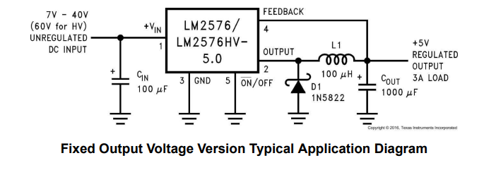
This is a typical application diagram of the LM2576 fixed - output voltage version. It takes 7V - 40V (60V for HV) unregulated DC input. Key components include input capacitor CIN (100μF), inductor L1 (100μH), free - wheeling diode D1 (1N5822), and output capacitor COUT (1000μF), providing +5V regulated output for 3A load.
1.2-V to 55-V Adjustable 3-A Power Supply With Low Output Ripple
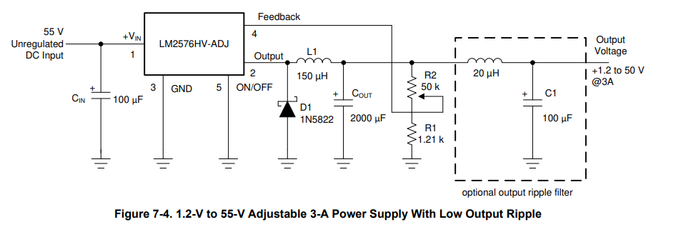
This is a 1.2 - 55V adjustable 3A power supply circuit using LM2576HV - ADJ. It takes 55V unregulated DC input, with components like CIN (100μF), L1 (150μH), D1 (1N5822), COUT (2000μF), and R1/R2 for voltage adjustment. An optional ripple filter (20μH inductor + 100μF capacitor) reduces output ripple.
Inverting Buck-Boost Develops −12 V
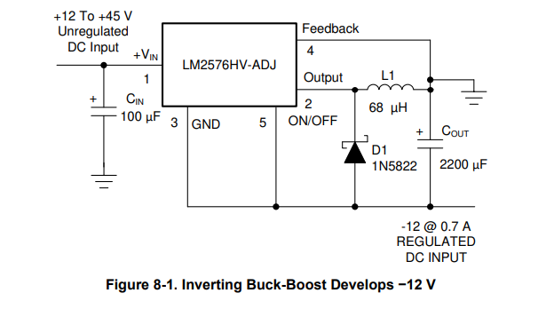
This is an inverting buck - boost circuit using LM2576HV - ADJ. It takes +12 to +45V unregulated DC input. Components like CIN (100μF), L1 (68μH), D1 (1N5822), and COUT (2200μF) work with the chip to generate a regulated - 12V output at 0.7A, enabling voltage inversion and regulation.
How to Use LM2576?
1. Requirements Analysis
First, determine the input voltage range, output voltage value, and maximum load current. For example, if the input voltage varies from 7V to 40V, and you need a stable 5V output with a maximum load current of 1A, select the appropriate LM2576 model. Fixed - output models like LM2576T - 5.0 can be chosen for simple applications; for adjustable output needs, the adjustable version is more suitable.
2. Component Selection
Inductor: Based on input and output voltages and the 52kHz switching frequency, calculate the required inductance value. Usually, a 33μH inductor is a common choice, but ensure its saturation current exceeds the maximum output current and has a low DC resistance.
Capacitors: Select input and output capacitors according to ripple requirements. Input capacitor C1 often combines a 10μF electrolytic capacitor and a 0.1μF ceramic capacitor to filter input noise. Output capacitor C2 uses a 100μF electrolytic capacitor and a 0.1μF ceramic capacitor to reduce output ripple.
Free - wheeling Diode: Choose a suitable diode like 1N5822. Its reverse - breakdown voltage should be higher than the maximum input voltage, and the forward - current rating should meet the output current demand.
3. Circuit Design and PCB Layout
Draw a detailed circuit schematic according to the typical application circuit. When laying out the PCB, separate the power path from the signal path. The power path should be short and thick to reduce resistance and inductance. Use single - point grounding or a ground plane for reliable grounding. For TO - 220 packages, reserve enough space for heat sinks in high - power applications.
4. Debugging and Testing
After making the prototype, test the output voltage, ripple, and efficiency. If the output voltage is unstable or the ripple is too large, check component connections, component values, and PCB layout for possible interference or incorrect selections, and make timely adjustments.
Troubleshooting Common Issues
Excessive output ripple: This may be caused by insufficient output capacitor capacity, inappropriate capacitor type, or 不合理 wiring. Try increasing the capacity of the output capacitor, using capacitors with low equivalent series resistance (ESR), or optimizing the wiring to shorten the length of power paths and signal paths.
Unstable voltage: This may result from interference in the feedback circuit, improper selection of inductors or capacitors, or excessive fluctuation of the input voltage. Check whether the wiring of the feedback pin is reasonable, replace with suitable inductors and capacitors, or add a filter circuit at the input end to stabilize the input voltage.
Low efficiency: This may be caused by excessive forward voltage drop of the freewheeling diode, excessive DC resistance of the inductor, or excessive on-resistance of the switching transistor. Use Schottky diodes with low forward voltage drop, inductors with low DC resistance, or check whether the chip is operating at the normal switching frequency.
Equivalents for LM2576
LM1117
Type and voltage regulation mode: Low dropout linear regulator (LDO). It stabilizes the output voltage by adjusting the voltage drop of internal transistors. Compared with switching regulators, it has smaller output voltage ripple.
Output voltage: Available in various fixed output voltage versions, such as 1.8V, 2.5V, 3.3V, etc. There is also an adjustable version, which can set the output voltage through external resistors, with the output voltage range generally around 1.25V - 5V.
Output current: The typical output current is 800mA, and some enhanced versions can reach 1A. It is suitable for circuits sensitive to power noise and with small load current, such as microcontroller systems and audio circuits.
Dropout voltage characteristic: The dropout voltage is low, usually around 1.2V under full load. Its efficiency is higher than that of ordinary linear regulators but lower than that of switching regulators.
CS51411
Type and voltage regulation mode: It belongs to switching regulators, generally using PWM (Pulse Width Modulation) to adjust the output voltage, which can achieve high conversion efficiency.
Output voltage: The adjustable range of output voltage is wide, which can meet various voltage requirements and adapt to more complex power supply design scenarios.
Output current: It has strong output current capability and can provide large load driving capacity, suitable for circuits with high power requirements.
Other characteristics: Usually integrated with multiple protection functions, such as overcurrent protection, overvoltage protection and overtemperature protection. It may also have fast transient response capability to cope with rapid changes in load.
LM723
Type and voltage regulation mode: It is a general-purpose linear voltage regulator, which can be used as a positive voltage regulator or a negative voltage regulator through appropriate external circuit configuration. It stabilizes the output voltage by means of error amplification and feedback control.
Output voltage: The output voltage adjustment range is wide, from 2V to 37V, and the output voltage can be flexibly set through an external resistor network.
Output current: Its own output current capability is limited, generally around tens of milliamperes, but it can expand the output current by connecting external power transistors to drive larger loads.
Application scenarios: Due to its flexibility, it is often used in laboratory power supplies, industrial control equipment and other occasions that have certain requirements for voltage regulation accuracy and do not have particularly large load current.
LM7912
Type and voltage regulation mode: Three-terminal fixed negative voltage regulator. It can convert the input DC voltage into a stable -12V output voltage and keep the output voltage stable through the adjustment of internal circuits.
Output voltage: Fixed output of -12V, non-adjustable.
Output current: The maximum output current is generally 1A, which can meet some circuits that need negative power supply and have current demand within this range, such as the negative power supply of operational amplifiers.
Application scenarios: Often used in electronic devices that need stable -12V power supply, such as audio power amplifier circuits, to provide negative power supply for related chips.
LM2576 Package Information
The LM2576 is available in several main package types:
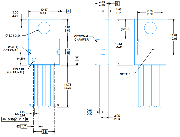
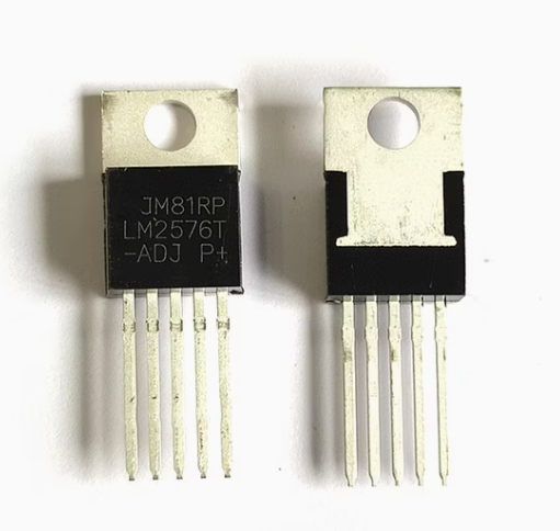
TO-220 package (LM2576T): This is a commonly used through-hole package with good heat dissipation performance, suitable for cooling via a heatsink. Its pin layout is clear, facilitating manual soldering and installation.
TO-263 package: A surface-mount package, ideal for automated production. It occupies less PCB space but has slightly inferior heat dissipation performance compared to the TO-220 package.
Different packages have varying thermal resistance parameters. The junction-to-ambient thermal resistance of the TO-220 package is typically around 60°C/W (without a heatsink), which can be significantly reduced by adding a heatsink. When designing a thermal solution, the appropriate heatsink size and type should be selected based on the chip’s power consumption and operating ambient temperature to ensure the chip’s junction temperature remains within the specified range.
LM2576 Datasheet
Conclusion
In conclusion, the LM2576 stands as a timeless and reliable solution in the realm of step-down voltage regulation, balancing efficiency, versatility, and ease of design. Its wide input range, flexible output options, and robust protection mechanisms make it a staple in diverse applications—from industrial control to automotive and consumer electronics.
Whether you’re an engineer designing a compact power module or an enthusiast prototyping a battery-powered device, understanding its features, working principles, and design nuances unlocks its full potential. While newer regulators may offer higher frequencies or smaller footprints, the LM2576 remains a go-to choice for its proven performance and accessibility.
By leveraging the insights in this guide—from component selection to PCB layout—you can harness its capabilities to build stable, efficient power systems. As technology evolves, the LM2576’s legacy endures, a testament to its enduring value in power management.




 Wishlist (0 Items)