

- RFQ
- BOM
-
Contact Us
Tel: +86-0755-83501315
Email: sales@sic-components.com


- Chinese
- English
- French
- German
- Portuguese
- Spanish
- Russian
- Japanese
- Korean
- Arabic
- Irish
- Greek
- Turkish
- Italian
- Danish
- Romanian
- Indonesian
- Czech
- Afrikaans
- Swedish
- Polish
- Basque
- Catalan
- Esperanto
- Hindi
- Lao
- Albanian
- Amharic
- Armenian
- Azerbaijani
- Belarusian
- Bengali
- Bosnian
- Bulgarian
- Cebuano
- Chichewa
- Corsican
- Croatian
- Dutch
- Estonian
- Filipino
- Finnish
- Frisian
- Galician
- Georgian
- Gujarati
- Haitian
- Hausa
- Hawaiian
- Hebrew
- Hmong
- Hungarian
- Icelandic
- Igbo
- Javanese
- Kannada
- Kazakh
- Khmer
- Kurdish
- Kyrgyz
- Latin
- Latvian
- Lithuanian
- Luxembou..
- Macedonian
- Malagasy
- Malay
- Malayalam
- Maltese
- Maori
- Marathi
- Mongolian
- Burmese
- Nepali
- Norwegian
- Pashto
- Persian
- Punjabi
- Serbian
- Sesotho
- Sinhala
- Slovak
- Slovenian
- Somali
- Samoan
- Scots Gaelic
- Shona
- Sindhi
- Sundanese
- Swahili
- Tajik
- Tamil
- Telugu
- Thai
- Ukrainian
- Urdu
- Uzbek
- Vietnamese
- Welsh
- Xhosa
- Yiddish
- Yoruba
- Zulu
- Kinyarwanda
- Tatar
- Oriya
- Turkmen
- Uyghur
Capacitor Size Chart: The Ultimate Guide To Capacitor Sizes
Summary: This article provides an in-depth and comprehensive introduction to capacitors as electronic components, detailing the critical impact of their size on circuit and device performance. It covers not only the fundamental concepts, types, and size standards of capacitors but also offers a meticulous interpretation of their specific size requirements in various application scenarios, as well as compatibility considerations during replacement. The aim is to help readers thoroughly understand the significance of capacitor size selection and enable them to choose and use capacitors correctly and appropriately in practical applications.
As one of the three passive electronic components, a capacitor is an energy storage element composed of two conductive electrodes and an insulating medium between them. Its basic characteristics can be expressed by the formula:
C = ε·A/d
Where:
C: Capacitance (Farad, F)
ε: Dielectric constant
A: Plate area
d: Plate spacing
Analysis of Core Parameters
Parameter Definition Typical Unit Importance
Capacitance The ability to store charge μF/nF/pF Determines the amount of energy stored
Voltage Rating The maximum operating voltage V Ensures safe operation
Tolerance The range of capacitance deviation % Affects circuit accuracy
ESR (Equivalent Series Resistance) Equivalent series resistance Ω Crucial for high-frequency performance
Overview of Capacitor Types
Classification of Fixed Capacitors
Ceramic Capacitors:
Characteristics: Small size, good high-frequency characteristics
Capacitance range: 1pF~100μF
Typical packages: 0402/0603/0805, etc.
Electrolytic Capacitors:
Aluminum electrolytic: Large capacitance (1μF~10000μF)
Tantalum electrolytic: High stability (1μF~1000μF)
Applications: Power supply filtering, energy storage
Film Capacitors:
Types: Polyester film/Polypropylene film
Characteristics: Low loss, high precision
Suitable for: High-frequency circuits, filtering networks
Variable Capacitors
Adjustable range: 5~500pF
Application scenarios: RF tuning circuits
Ceramic Capacitors VS. Electrolytic Capacitors VS. Film Capacitors
Type Capacitance Range Voltage Range Temperature Characteristics Typical Applications
Ceramic 1pF-100μF 6.3V-10kV X7R/X5R stable High-frequency decoupling
Electrolytic 0.1μF-1F 6.3-500V Poor Power supply filtering
Film 1nF-100μF 50-2000V Excellent Precision analog circuits
Detailed Explanation of Size Specification
SMD Standard Size Comparison Table
Package Code Metric Size (mm) Imperial Size (inch) Typical Capacitance Range
01005 0.4×0.2 0.016×0.008 0.1pF~1nF
0402 1.0×0.5 0.016×0.008 0.1pF~10nF
0603 1.6×0.8 0.06×0.03 1pF~100nF
0805 2.0×1.25 0.08×0.05 10pF~1μF
Size Specifications of Electrolytic Capacitors
Diameter: 5mm~50mm
Height: 10mm~100mm
Capacitance-volume ratio: Approximately 100μF/cm³ (Aluminum electrolytic)
Professional Selection Methodology
1. Principle of Capacitance Calculation
For Power Supply Filtering Applications:
C ≥ (I·Δt)/ΔV
Where:
I: Load current
Δt: Discharge time
ΔV: Allowable ripple voltage
For Motor Starting Capacitors:
Empirical formula: C(μF) ≈ (1000·P)/(V²·2πf)
P: Power (W), V: Voltage (V), f: Frequency (Hz)
2. Principles for Voltage Rating Selection
Operating voltage ≤ 80% of the rated voltage
Transient voltage ≤ Rated voltage
Derating curve reference:
In an 85℃ environment: Derate by 20%
In a 105℃ environment: Derate by 40%
Industry Application Specifications
1. Capacitor Selection Table for HVAC Systems
Equipment Type Capacitance Range (μF) Voltage Level (V) Size Reference (mm)
1 HP air conditioner 20~30 370~440 Φ30×50
3 HP air conditioner 40~50 440~480 Φ35×60
5 HP air conditioner 60~80 480~550 Φ40×80
2. Specifications for Motor Starting Capacitors
Motor Power (HP) Starting Capacitor (μF) Running Capacitor (μF)
1/4 50~75 4~10
1/2 100~125 10~20
1 150~200 20~30
3. Switching Power Supply Design
Input Filtering: X2 safety capacitor (100nF - 1μF)
Output Filtering: Low ESR electrolytic capacitor (220 - 1000μF)
High-frequency Decoupling: Ceramic capacitor (0.1μF, 0805 package)
4. Internet of Things (IoT) Devices
RF Matching: 1 - 10pF NP0 ceramic capacitor
Power Management: 10μF 0603 MLCC (Multilayer Ceramic Capacitor)
RTC (Real-Time Clock) Backup: 0.1F supercapacitor
Key Points in Engineering Practice
1. Installation Precautions
Polarity Confirmation: The positive and negative poles of electrolytic capacitors must be strictly distinguished.
Spacing Maintenance: High-voltage capacitors need to ensure sufficient creepage distance.
Thermal Management:
Keep away from heat sources.
Install heat sinks for high-current applications.
Mechanical Fixation: Special brackets are required for large capacitors.
2. Analysis of Failure Modes
Capacitance Decay: Caused by the drying up of the electrolyte (approximately 5~10% per year)
Increase in ESR: Caused by the aging of the dielectric
Short-circuit Failure: Caused by dielectric breakdown
Open-circuit Fault: Caused by the breakage of the lead wire
Development of Cutting-edge Technologies
1. New Capacitor Technologies
Supercapacitors:
Capacitance: 0.1~3000F
Characteristics: High power density (10kW/kg)
Applications: New energy storage, instantaneous large current power supply
Progress in MLCC Technology:
Ultra-thin dielectric: <1μm
High capacitance and miniaturization: 100μF/0805 package
Solid Electrolytic Capacitors:
Service life: >50,000 hours
ESR: Reduced by more than 50%
Frequently Asked Questions
Q: Can a capacitor with a larger capacitance be used to replace the original specification?
A: Comprehensive considerations are required:
The voltage rating must be ≥ the original specification.
The physical size needs to be suitable for the installation space.
In high-frequency applications, pay attention to the change in ESR.
For power supply filtering, it can be appropriately increased (+20%).
Q: Can capacitors of different materials be used interchangeably?
A: Principles:
For high-frequency decoupling: Ceramic capacitors are preferred.
For large-capacity energy storage: Electrolytic capacitors are necessary.
In key timing circuits: Avoid mixing capacitors with different temperature characteristics.
Q: How to determine if a capacitor is aging?
A: Detection methods:
Capacitance test: Replace if it deviates from the nominal value by >20%.
ESR measurement: Replace if it exceeds twice the initial value.
Appearance inspection: Replace immediately if there is bulging or leakage.
This technical guide comprehensively covers all key aspects of capacitors, from basic theories to engineering practices, providing a complete selection and application reference system for electronic engineers. In actual design, it is recommended to combine specific application scenarios, refer to the latest specification sheets provided by manufacturers, and fully consider the impact of environmental factors on the performance of capacitors to achieve the optimal circuit design.
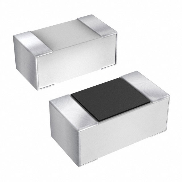
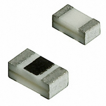
Welcome to our collection of common capacitor sizes! Whether you are a hobbyist, technician, or engineer, you will find the perfect capacitor for your electronic projects and devices. Our range includes the most widely used capacitance values, ensuring that you have the right component for your application. From tiny ceramic capacitors suitable for compact circuit designs to larger electrolytic capacitors for power supply and filtering applications, we have a variety of sizes to accommodate various needs. Each capacitor is designed to provide reliable and stable performance, meeting industry standards for quality and efficiency. Our common capacitor sizes are suitable for a wide range of electronic equipment, including audio amplifiers, power supplies, LED lighting, motor control systems, and more. With our comprehensive selection, you can easily find the right capacitor for your specific requirements, making your projects easier and more efficient. Discover the perfect common capacitor sizes for your electronic needs today!
https://www.sic-components.com/capacitors

Hot Products
View More-
04023J2R0ABSTR KYOCERA AVX
-
12101K100GBTTR KYOCERA AVX
-
08051J6R2CBTTR KYOCERA AVX
-

06033J0R9PBSTR\500 KYOCERA AVX
-
06033J130FBSTR KYOCERA AVX
-
04023J0R5ZBSTR\500 KYOCERA AVX
-
0402ZJ120GBWTR KYOCERA AVX
-
04023J0R4ABWTR\500 KYOCERA AVX
-
06031J0R2PBSTR\500 KYOCERA AVX
-
04021J1R0BBSTR KYOCERA AVX
-
08051K1R2CAWTR KYOCERA AVX
-
04023J2R0ABSTR\500 KYOCERA AVX
Related Blogs
-
2025 / 04 / 19
Analog Devices ADXL345BCCZ Accelerometers
The Analog Devices ADXL345BCCZ is a 3 - axis digital accelerometer. It features ultralow power consumption, with only 23 µA in measurement mode. Offering user - selectable resolutions up to 13 - bit at ±16 g, it enables accurate motion sensing. It supports SPI and I²C interfaces, and has functio...
-
2025 / 04 / 17
Analog Devices ADA4505-2ACBZ-R7 Operational Amplifiers
The Analog Devices ADA4505-2ACBZ-R7 is a dual-channel, micropower operational amplifier. It features low supply current (max 10 μA per channel), wide supply voltage range (1.8V - 5V single or ±0.9V - ±2.5V dual). With rail-to-rail input and output, high PSRR (min 100 dB) and CMRR (typ 105 dB), it of...
-
2025 / 04 / 15
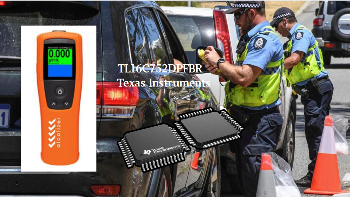
TL16C752DPFBR | Texas Instruments | UART Interfaces
The Texas Instruments TL16C752DPFBR is a dual universal asynchronous receiver transmitter (UART). It comes with 64 - byte FIFOs per channel, reducing the load on the connected processor. Operating at data rates up to 3 Mbps, it suits high - speed communication scenarios. With a wide supply voltage r...
-
2025 / 04 / 12
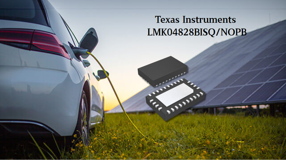
Texas Instruments LMK04828BISQ/NOPB-Clock, Timing & Frequency ICs
The Texas Instruments LMK04828BISQ/NOPB is a high-performance clock jitter cleaner. With a dual-loop PLL architecture, it offers ultra-low RMS jitter (88fs in 12kHz - 20MHz). Supporting JEDEC JESD204B, it can drive 7 target devices. It provides 15 differential clock outputs up to 3.1GHz, with progra...
-
2025 / 04 / 10
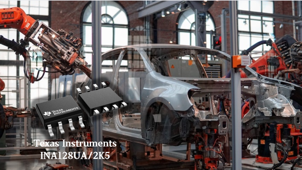
Texas Instruments INA128UA/2K5 - Amplifiers/Comparators
The Texas Instruments INA128UA/2K5 is a precision instrumentation amplifier. It features a low offset voltage (in the range of several tens of microvolts) and low drift characteristics, ensuring the precise amplification of small signals. With a high common-mode rejection ratio (exceeding 120 dB), i...
-
2025 / 04 / 08
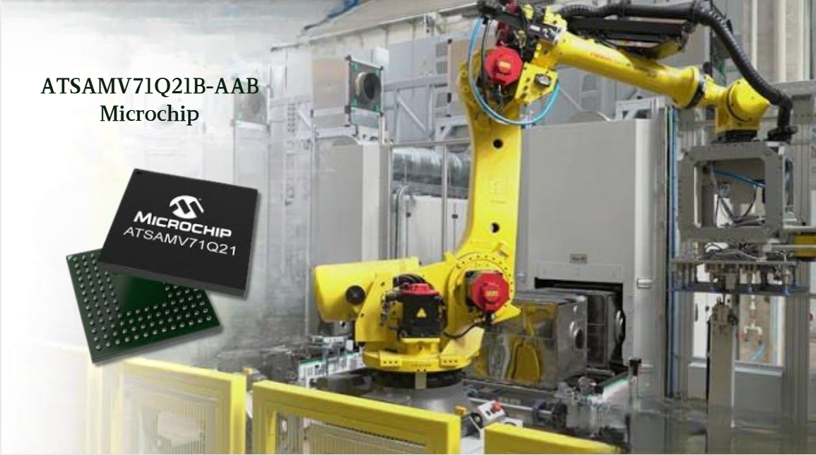
ATSAMV71Q21B-AAB Microchip 32bit MCU
The ATSAMV71Q21B-AAB from Microchip is a powerful microcontroller. Based on the Arm® Cortex®-M7 core, it operates at a frequency of up to 300 MHz, enabling efficient computing. It integrates 2048 KB of flash memory and 384 KB of multi-port SRAM, ensuring data storage and fast read-write operations. ...
-
2025 / 04 / 03
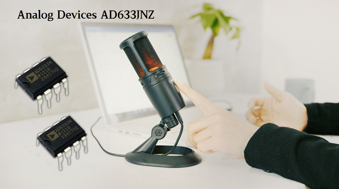
AD633JNZ Analog Devices-Analog Multipliers, Dividers
The Analog Devices AD633JNZ is a high - performance analog multiplier. Housed in an 8 - lead PDIP package, it features 4 - quadrant multiplication. Requiring no external components, it simplifies circuit design. Laser - trimmed for accuracy, it has low total error. With differential high impedance i...
-
2025 / 04 / 01
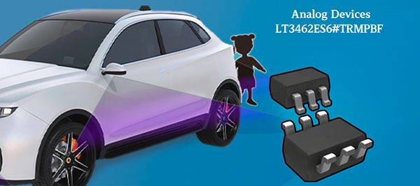
LT3462ES6#TRMPBF Analog Devices Inc. - DC to DC Converter
The LT3462ES6#TRMPBF by Analog Devices Inc is a fixed - frequency inverting DC/DC converter. It integrates a Schottky rectifier and has a low VCESAT switch. With a 1.2MHz switching frequency, it can generate negative output voltages like -5V at 100mA from 5V input. It's used in applications such as ...
-
2025 / 03 / 29
LTC2430IGN#PBF Analog Devices-Analog to Digital Converters
The LTC2430IGN#PBF is a highly versatile analog-to-digital converter with impressive specifications. Operating at a wide voltage range of 2.7V to 5.5V, this micropower converter boasts 20-bit resolution and 3ppm integral nonlinearity (INL). Its low noise level of 0.56ppm RMS ensures accurate and rel...

-
2025 / 03 / 27
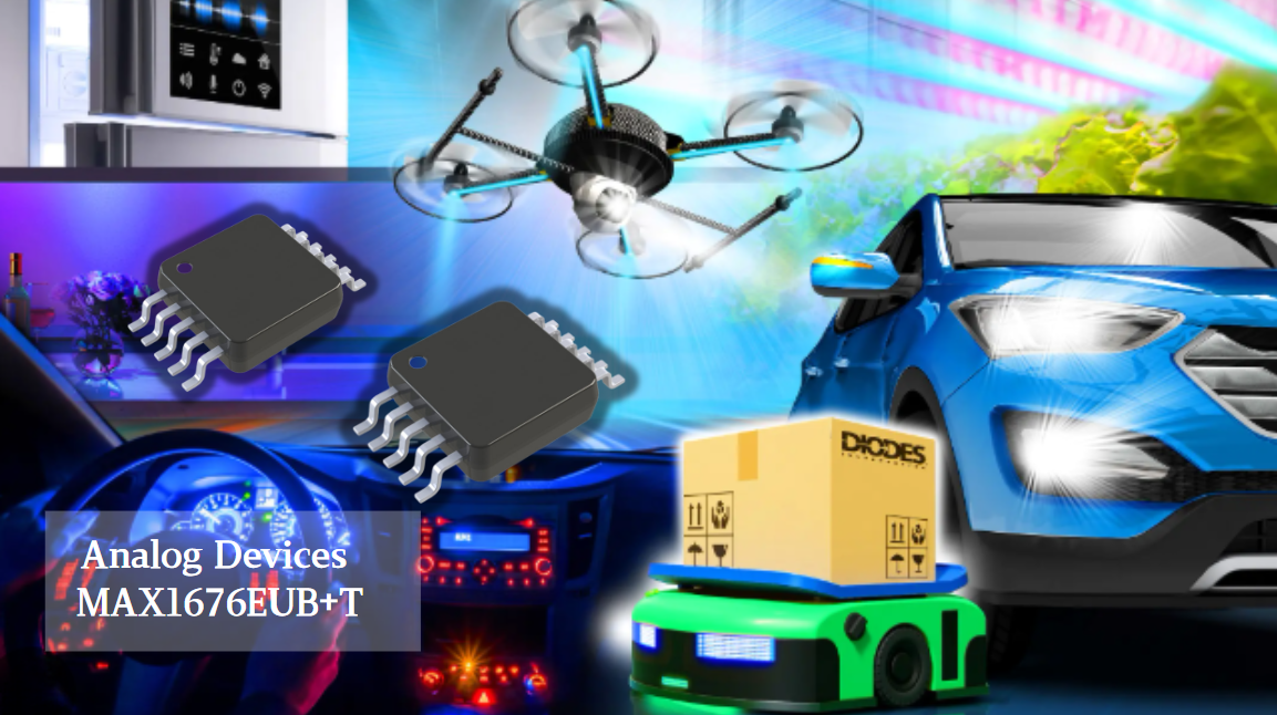
MAX1676EUB+T Analog Devices / Maxim Integrated-Voltage Regulators ICS
The Analog Devices / Maxim Integrated MAX1676EUB+T is a compact, high - efficiency step - up DC - DC converter. It has a quiescent supply current of just 16µA and can reach up to 94% efficiency at 200mA output. Its input voltage spans from 0.7V to VOUT (adjustable from 2V - 5.5V). With an adjustable...

2000+
Daily average RFQ Volume

30,000,000
Standard Product Unit

2800+
Worldwide Manufacturers

15,000 m2
In-stock Warehouse
 Wishlist (0 Items)